
Service Manual


DRIVE SYSTEM
4 - 4 Snow Commander Service Manual
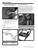
8. To remove the brake arm, first unhook the brake
spring (Figure 46). The brake arm is attached by a
single shoulder bolt through the side plate (Figure
47). Remove the locknut and large washer. Pull
the brake arm off carefully as there is a pivot
washer between the brake arm and side plate.
Figure 46
3428-0240
Figure 47 3428-0243
9. Replace nylon rollers if worn or damaged. One is
retained by a cap nut (Figure 48). Use side
cutters to remove it, and replace with a new cap
nut.
Figure 48
3428-0236
Drive System Assembly
Assemble in reverse order. The following are tips to
assist you.
1. Many of the capscrews and nuts are the locking
type. However, the material in the threads that
provides the locking feature, wears out. If the parts
assemble easily, we suggest either replacing the
locknut or capscrew or, cleaning the screw
threads and applying a chemical thread locker
such as Loctite brand.
(A) Cap Nut
A