
Service Manual


Traction and Impeller Controls Inspection
1.
Inspect all bushings checking for wear and
replace as necessary.
2.
Check all rotating parts for corrosion and/or
excessive wear. Lubricate with an anti-seize
compound (Toro
part
number
505-109)
or replace
as necessary.
3.
Check the trip lever and release cam to insure that
the keys securing them to the cross rod are still
intact.
5.
Push the cross rod through the impeller lever
bushing until
it
protrudes-about
13
mm
(1/2").
6.
Find the traction cable and install
it
and the
extension spring into the release cam as shown in
Figure
52.
NOTE: The recessed side of the release
cam
will
face the control panel.
7.
Hook the extension spring into the slot provided
in the right handle then mount the release cam
onto the cross rod.
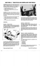
Traction and Impeller Controls Reassembly
See Figure
50.
Figure
50
1.
Position the traction lever in
its
normal location on
the
left
handle and press in the traction lever
bushing.
NOTE: The traction lever bushing is reversible.
2.
Place
the
traction lever spacer inside the traction
lever and insert the cross rod through the traction
lever.
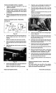
3.
Install the trip lever onto the cross rod as shown
in Figure
51.
Figure
51
Figure
52
8.
Fasten the impeller cable to the locking tang
as
shown in Figure
52.
9.
Position the locking tang inside the impeller lever
and then push the cross rod all the way through.
Secure with the Phillips screw.
10.
Install
the
torsion spring and the lock latch onto
the spindle and secure with the E-clip. See Figure
52
for proper spring orientation.
11.
Position both traction and impeller cables into the
cable holder,
but
do not tighten at this time.
12.
Secure the cross rod to the traction lever with the
hex head screw and locknut.
13.
Before assembling any further, verify that
everything works as described under Traction
and Impeller Controls Operation, page
50.
14.
Install a new push nut on the right end of the cross
rod. Be sure to align the tabs in the push nut
90"
from the keyway to insure retention.
15.
Install the locking mechanism cover with the
two
screws.
Traction and Impeller Controls Traction Cable
Adjustment
A
4.
Position the impeller lever on the right handle and
The
traction
system
very
little
of
the
available
power from the engine. Therefore, the belt doesn't
press in the impeller lever bushing.
NOTE: The impeller lever bushing is reversible. require much tension to drive the wheels.
Traction and Impeller Controls
52
Power
Shift
Snowthrowers