
Service Manual


Transmission Operation (cont'd)
Figure
76
The four gears are driven by the gears opposite them
on the intermediate shaft. The selectable gears rotate
freely on the sleeves when the transmission is in neutral.
However, when the transmission is in gear, the shift
mechanism engages
one
of the gears
so
that the gear
and the sleeves rotate together.
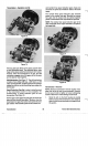
Shift Mechanism: See Figure
77.
The shift mechanism
consists of
two
sliding shift keys, a shift sleeve, a shift
collar and the shift fork. Control input from the operator
rotates the shift fork
so
that the sliding keys engage the
desired gear.
Speed Reduction Gear Set: In order to bring the speed
of the transmission down to one acceptable for
snowthrowing, a speed reduction gear set was
incorporated. See Figure
78.
The first gear in the speed reduction gear set is also the
sleeve in which the shift keys slide. Therefore, when the
transmission is in gear, the number one speed reduction
gear rotates. This transmits power to the number
two
and number three speed reduction gears. Gears
two
and three are joined and therefore rotate at the same
speed.
The number three speed reduction gear transmits
power to
the
number four gear. Because the number
four gear and the output shaft are splined together,
power is transmitted to the output shaft and sprocket.
NOTE: The number four speed reduction gear is the
only component on the output shaft that
is
coupled to
the output
shaft.
Figure
77
Figure
78
Transmission Removal
NOTE:
Because transmission removal requires many
steps, the use of air tools is recommended. However,
do not use air tools to tighten or loosen self-tapping
screws in aluminum. Thread damage could result.
1.
Stand the unit on the front housing to provide
better access to the transmission. Don't forget to
drain the fuel first as described at the beginning of
this section.
Transmission
64
Power Shift Snowthrowers