
Service Manual


Control
Box
Operation Reverse Control (cont'd)
When Power Shifting
the
wheels forward, the indexing
The
index
wheel
is
necessary because
the
wheels must
mechanism does nothing but index. The tabs On the
alternate between forward backward movement
bottom
Of
the index wheel miss the tab On the reverse
when Power Shifting. bellcrank and the wheels power forward when the
traction lever is engaged.
See
Figure
20.
Control
Box
Operation Shift
Lockout
Transmission damage could result
if
the operator were
to shift the transmission into reverse while the unit were
moving forward and vice versa. To prevent this, a shift
lockout is used. This lockout physically prevents the
operator from switching directions without first stopping
the unit.
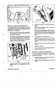
The lockout base pivots on a shoulder bolt and rotates
whenever the shift lever is moved to either the Power
Shift or reverse slots. See Figure Note however, that 19.
the lockout base does not rotate when the gearshift lever
is
moved from side to side.
Figure 19
When
the
traction lever on the left handle
is
not
engaged, the
lockout
base
is
free
to
move in either
direction. However, once the traction lever is engaged,
the
two
tabs on the lockout lever engage the lockout
base. This prevents the shift lever from being moved
forward or backward.
An added benefit
of
the shift lockout is that
it
allows the
operator to lock the gearshift lever in either the Power
Shift or reverse slots by depressing the traction lever.
This allows the operator one hand operation
of
Power
Shift or reverse leaving the other hand free to rotate the
chute.
Control
Box
Operation Indexing Mechanism
An indexing mechanism is used
to
control the direction
of wheel movement while Power Shifting. This
is
necessary because the wheels need to alternate
between forward and reverse when the Power Shift
is
cycled.
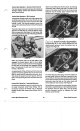
Figure 20
When the wheels are to be moved to the rear position,
a
tab on the bottom of the index wheel contacts a
corresponding tab on the reverse bellcrank and the
wheels power backward when the traction lever
is
engaged. See Figure 21.
Figure
21
The index tang and a flat spring control the rotation of
the index wheel. When the shift lever is pushed into the
Power Shift slot, the index tang rotates the index wheel
1/8
revolution and then prevents the wheel from rotating
backwards when the tabs on the index wheel and
reverse bellcrank make contact. See Figure
22.
As
the shift lever returns to its "at rest" position,
the
index
wheel has a natural tendency to turn backwards due to
the pressure from the index tang. The flat spring
prevents backward rotation by engaging the index
wheel at one of the teeth.
Power Shift Snowthrowers
43
Power Shift Controls