
Service Manual


29
FUEL SYSTEM
Operation
The E en
g
ine uses a plastic fuel tank with a non-
replaceable 75 micron in-tank filter screen. The filter is
welded in the bottom of the tank over a sediment
reservoir. The tank is mounted above the level of the
carburetor and uses
g
ravity to supply fuel throu
g
h a
.25" I.D. (6.35 mm) rubber hose to the carburetor. The
fuel hose is friction-fitted to the tank outlet at one end
and to the carburetor at the other end.
The fuel tank is vented throu
g
h an openin
g
in the fuel
cap. The fuel openin
g
on the tank is opposite the fuel
outlet, helpin
g
to prevent dama
g
e to the filter screen by
funnels and
g
asoline filler spouts that may be inserted
into the fuel tank durin
g
refuelin
g
. The placement of
the cap also prevents interference with the startin
g
rope in Zone Start mower applications.
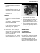
The fuel cap is a four piece desi
g
n (see Fi
g
ure 44) with
an inner sealin
g
disc that is vented to a baffle assembly
in the body of the cap. The baffle assembly allows
expansion in the tank or splash a
g
ainst the bottom of
the cap, without the loss of fuel. Atmospheric pressure
is allowed into the tank from an openin
g
in the cap to
allow
g
ravity to feed fuel to the carburetor. (If an
individual part of the cap fails, the entire assembly
must be replaced.)
Fi
g
ure 44
0720-022
Fuel Cap Service
1. The fuel cap may not be disassembled; however,
the vent openin
g
on the cap and inner sealin
g
disc
should be kept free of debris.
2. The ventin
g
ability of the cap may be tested by
fillin
g
the cap with water and observin
g
the flow of
water out of the vent openin
g
in the top of the cap.
If water does not drain, the vent openin
g
may be
plu
gg
ed or restricted.
3. If the fuel cap will not vent properly, replace the
entire cap assembly.
4. Should you encounter a situation where fuel leaks
around the threads of the fuel cap (not out the
vent), inspect the top of the neck of the fuel tank
and the area in the cap where the fuel tank neck
contacts the cap. This is the sealin
g
area, not the
threads. (See Fi
g
ure 45.)
Fi
g
ure 45
720-021
Cleaning
1. Remove the fuel tank. Take it to an appropriate
area, and wash the tank in clean solvent intended
for cleanin
g
en
g
ine parts.
2. Backwash the filter screen by directin
g
cleanin
g
solvent, under moderate pressure, throu
g
h the
sediment reservoir and screen, opposite the
direction of fuel flow.
3. Wash the tank a
g
ain with clean solvent.
4. Clean or replace the fuel hose.