Service Manual

Single Stage Snowthrower Service Manual 5 - 19
DRIVE SYSTEMS
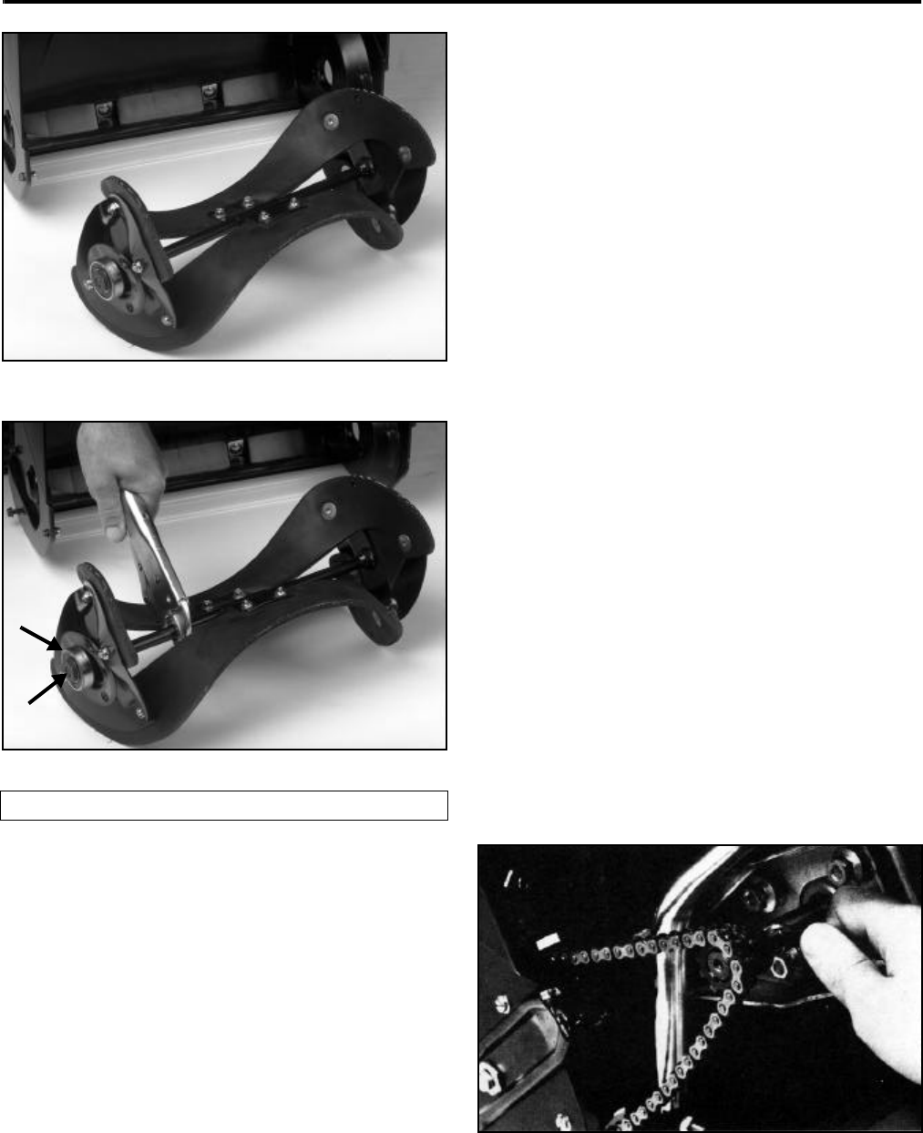
Figure 102 1854-22
Figure 103 1854-21
NOTE: Do not damage the splines or threads in an
attempt to hold the shaft while removing the nut.
New bearings can now be installed on the shaft.
Tighten the nut retaining the right side bearing
(opposite the drive) to 200 - 300 in·lbs.
Assembly
After the new bearings are installed, the rotor can be
reinstalled. Insert the drive side first and push the rotor
towards the drive side, spread the rotor housing, and
insert the non drive side into the hole in the housing.
20” CCR Style
The 20” CCR rotor has only minor differences when
compared to the Powerlite. The rotor pulley is attached
to the rotor shaft with a key and a bolt (later models
have the key built into the pulley). The bearing
retainers are slightly different in that some of them
have threaded studs in place of bolts. On the side
opposite the drive, the outer bearing flange is a
separate part. With the exception of these things, the
Powerlite procedure is used.
DRIVE SYSTEM (CHAIN) SNOW PUP -
S-140
The Toro chain drive system, found on all Toro 14” and
21” single stage snowthrowers has not changed to any
great degree since originally designed for the first
Snow Pup in 1965.
Lubrication:
All the bearings used on the Toro 14” and 21”
snowthrowers are lubricated for life at the factory and
require no additional lubrication. However, a few drops
of light machine oil on the drive chain once a year will
adequately lubricate the chain and sprockets.
Components And Operation
The major components to the 14” and 21” chain drive
system include the engine sprocket, impeller sprocket
and drive chain (Figure 104). Power is transferred
from the engine sprocket, which is keyed to the engine
crankshaft, by a chain to the larger impeller sprocket
fastened to the rotor halves.
Figure 104 0217-064
(A) Bearing (B) Nut
A
B


