
Service Manual


49
PIVOTING ZONE START BRAKE
Assembly
1. If the brake mountin
g
plate was not removed from
the en
g
ine, simply reconnect the
g
roundin
g
lead to
the push-on terminal directly above the
g
round
strap stop (4) and continue with the reassembly
process.
Note: If the brake mountin
g
plate was removed,
ti
g
hten screw (9) to 60 - 70 in. lbs. (6.78 - 7.91
Nm).
2. Secure the replacement brake plate to the en
g
ine
with shoulder screw (7). Ti
g
hten it to 90 in. lbs.
(9.2 Nm). Ensure that the brake plate pivots freely.
3. Slide the cable into the narrow slot on the brake
mountin
g
plate, and then push the cable into the
hole makin
g
sure the tabs lock into the bracket.
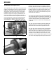
4. One end of the compression sprin
g
has a hook
shape to it; that end hooks over an indentation in
the brake plate. Squeeze the compression sprin
g
(A) and slip it over the cable between the brake
mountin
g
plate and brake plate. (See Fi
g
ure 90).
Fi
g
ure 90
0893-051a
5. Insert the leaded ball end of the cable into the
vertical slot (B) of the brake plate. (See Fi
g
ure 90.)
6. Operate the blade control bail to verify that the
brake mechanism stops within three (3) seconds.
There is no adjustment needed after this assembly
process is completed. (See Fi
g
ure 91).
Fi
g
ure 91
0891-1
A
B