Service Manual

Single Stage Snowthrower Service Manual 9 - 7
GAS POWER SHOVEL
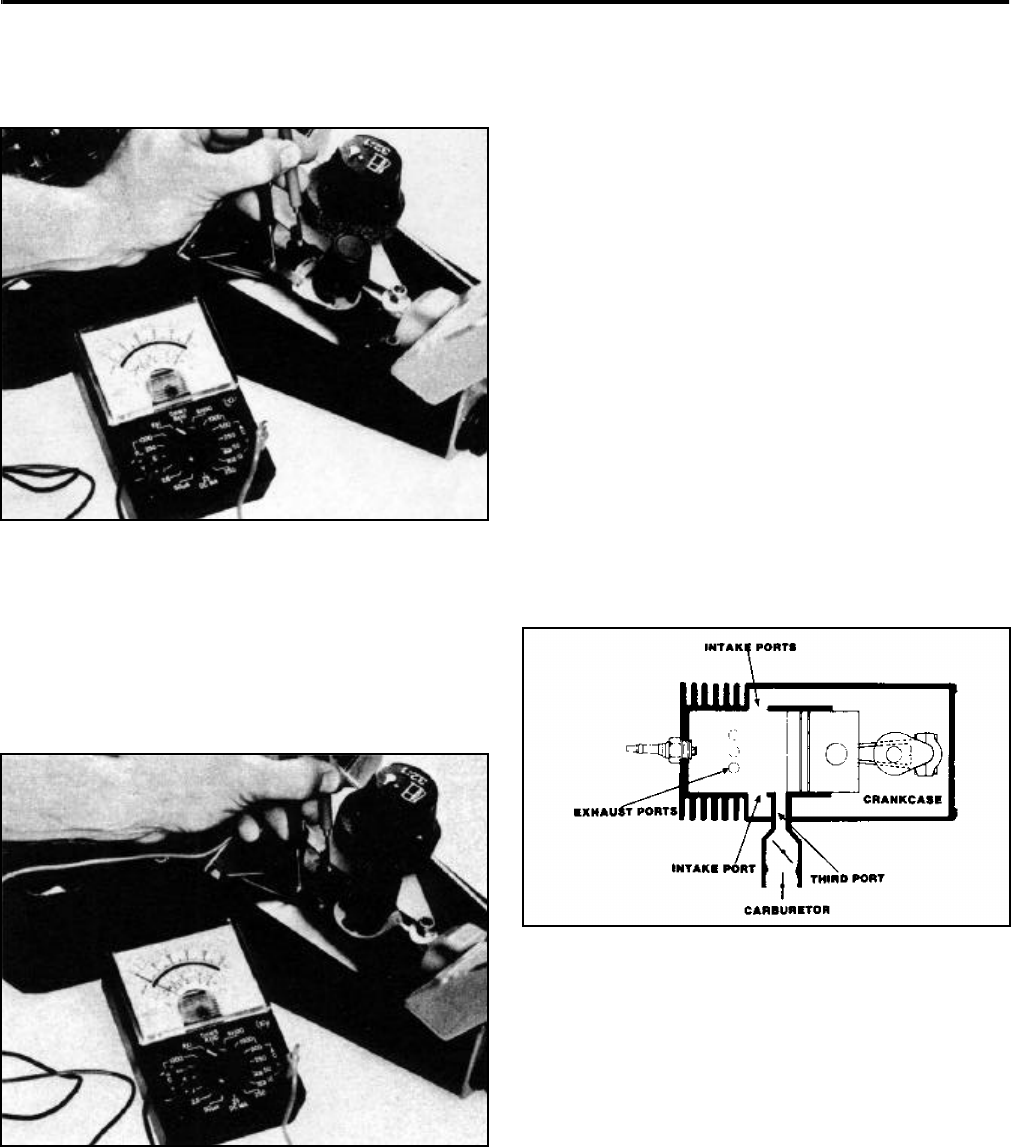
4. Place one continuity light or volt/ohmmeter lead to
each of the switches. The test instrument used
should register continuity (Figure 194).
Figure 194 0406-015
5. Now, turn the ignition switch to the “ON” or the 2
o’clock position. Visually check to ensure that the
switch actuator is not in contact with the contact
switch terminals. The tester should not register
continuity when the switch is in the “ON” position
(Figure 195). Switch parts which are loose, bent,
or damaged should be replaced.
Figure 195 0406-016
6. Connect the coil wire(s) to the switch and replace
the upper shroud.
ENGINE OPERATING THEORY
2-Cycle Engine – Theory Of Operation
2-cycle engines are used on the Toro Gas Power
Shovel because of their:
1. Lightweight.
2. Excellent power-to-weight ratio.
3. Ability to operate in any position.
4. Easy maintenance.
5. Simple construction.
The Toro 2-cycle engine used on Toro Gas Power
Shovels is a third-port, loop-scavenged design. This
design name describes the path of the fuel/air mixture
into the crankcase and combustion chamber, and the
exhausting of spent gases (Figure 196). The piston in
Figure 196 is shown in a lower than normal position, to
clearly show the individual ports.
Figure 196 0406-017


