
Operator's Manual


9
Installing
the Auger/Impeller
Drive Control Linkage
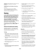
1. Loosen
the jam nut above the clevis on the upper
control rod (Fig. 8).
2.
Align the holes in the clevis and lower control rod and
insert the clevis pin (Fig. 8).
649
Figure
8
1. Jam
nut
2. Clevis
3.
Upper control rod
4.
Lower control rod
5.
Clevis pin
6.
Cotter pin
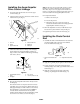
3. Check
the distance between the top of the handgrip
and the bottom of the auger/impeller control lever
(Figs. 6 and 9). The distance should be approximately
four inches (10 cm).
665
Figure
9
1. Auger/impeller
control
lever
2. Handgrip
3.
4 in. (10 cm)
4.
1 to 2 in. (2.5 to 5.1 cm)
4. Press
the auger/impeller control lever slowly toward
the handgrip.
The amount of force to compress the lever increases
noticeably when you remove the slack from the drive
belt (approximately one–half of the lever movement).
The adjustment is correct when the force
begins
to
increase and the distance between the top of the
handgrip and the bottom of the auger/impeller control
lever is one to two inches (2.5 to 5 cm) (Fig. 9).
Note: If
the force does not noticeably increase, remove
the belt cover (refer to
Replacing the Auger/Impeller
Drive Belt
, steps 1 and 2 on page 19) and measure two
inches (5.1 cm) above the handgrip at the point where you
remove the slack from the auger/impeller drive belt.
5. T
o adjust the distance:
A.
Remove the clevis pin.
B.
Loosen the jam nut.
C.
Thread the clevis up or down to increase or
decrease the distance between the handgrip and the
auger/impeller control lever (Fig. 8).
6.
When the adjustment is correct, install the clevis pin
and secure it in place with the cotter pin (Fig. 8).
7. T
ighten the jam nut to secure the clevis (Fig. 8).
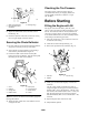
Installing
the Chute Control
Rod
1. Assemble
the chute control bracket and rod to the left
side of the handle with a capscrew and a locknut.
Leave the locknut loose (Fig. 10).
886
Figure
10
1. Chute
control bracket and
rod
2.
Capscrew and locknut
2. Apply
No. 2 general purpose grease to the worm gear
.
3.
Loosely mount the worm gear and bracket to the
mounting flange with a bolt, a pyramidal washer
, and a
locknut (Fig. 1
1).
4.
Slide the worm gear into the teeth of the chute
retaining ring and tighten the locknut (Fig. 1
1).