
Operator's Manual


12
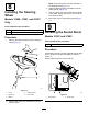
ConnectingtheBattery
Models31900,31901,and31907
Only
NoPartsRequired
Procedure
Connectthebattery;refertoConnectingtheBattery
(page54).
13
InstallingtheAttachment
Partsneededforthisprocedure:
1
Optionalattachment(orderedseparately;refertoyour
authorizedT orodistributor)
2
Socket-headscrew(3/8inch)
2
Washer(3/8inch)
2
Flangelocknut(3/8inch)
Procedure
Installthefrontattachment(e.g.,cuttingunit,plow
blade,orblower);performthefollowingstepsand
refertoyourattachmentOperator’sManualfor
additionalinstallationinstructions.
1.Whilesupportingthedriveshaft,removethe
capscrewandlocknutthatsecurethedriveshaft
yoketothesteeringvalve-mountbracket(Figure
17),andcarefullylowerthedriveshaft.
Note:Discardthecapscrewandlocknut.
g340623
Figure17
1.Capscrew
4.Locknut
2.Driveshaftyoke5.Frontofthemachine
3.Steeringvalve-mount
bracket
2.Haveanassistantsitintheseat,turnthekey
totheONposition,andusetheattachmentlift
switchtolowertheliftarmswhileyoupushdown
ontheliftarms.
3.Aligntheholesintheliftarmwiththeholesinthe
attachmentarmasdescribedintheattachment
InstallationInstructions.
4.Alignthesplinesinthedriveshaftyokeontothe
splinesoftheattachmentinputshaft(Figure18),
andslidetheyokeovertheshaft.
g340624
Figure18
1.Driveshaftyoke2.Inputshaft
5.Assembleasocket-headcapscrew(3/8x2-1/4
inches)throughawasher(3/8inch)andthehole
inthedriveshaftyoke(Figure19),andsecure
thecapscrewwithaange-locknut(3/8inch).
18