
Operator's Manual
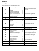


6.Performthefollowingstepstosecurethe
hydrauliccylinderstotheliftarms:
A.Placeadrainpanunderthehydraulic
manifold(showninFigure9).
Note:Youmustbleedasmallamountof
hydraulicuidinordertomanuallyretract
theliftcylinders.
g299920
Figure9
B.Loosenthehoseswivelnutconnectedto
portC1ofthehydraulicmanifold(Figure
10).
g312025
Figure10
1.Manifold
3.Hoseswivelnut
2.PortC1
C.Useadriftpunchtoalignthecylinderrod
holeswiththelift-armholes(Figure11).
Note:Fullyraisetheliftarmtohelpwith
thealignment.
g312026
Figure11
1.Bolt(3/8x1-1/4inches)3.Cylinderrod
2.Smallpin4.Nut(3/8inch)
D.Use2bolts(3/8x1-1/4inches),2nuts(3/8
inch),and2smallpinstosecurethelift
armstothecylinders(Figure11).
E.TorquethehoseswivelnutonportC1to
41N∙m(30ft-lb).
Note:Useabackupwrenchtopreventthe
hosefromtwisting.
7.Greasetheattachmentpinjointsandlift-arm
pinjoints;refertoGreasingtheBearingsand
Bushings(page49).
5
InstallingtheFrontTires
Models31900,31901,and31907
Only
NoPartsRequired
Procedure
1.Usethepreviously-removedlugnutstosecure
thetirestothewheelhubs(Figure12).
15