
Operator's Manual


g008868
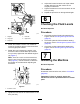
Figure7
1.Winglet4.Eccentric
2.Hingepin5.Upperhole
3.Stopbolt
3.Rotatetheforwardeccentricuntilitreaches
maximumclearancewiththeinner-slotsurface
ofthewinglet-pivotbracket.
4.Rotatetherear(closesttothetractionunit)
eccentricuntiltheoutsidebladetipisabout3
mm(1/8inch)higherthanthedesiredheightof
cut(Figure7).
Note:Thereisanotchontheeccentrichex,
whichis180°fromthelobeontheeccentric
cam(Figure8).Usethenotchestoreference
thelocationofthelobeswhenadjustingthe
eccentrics.
g009153
Figure8
1.Eccentricnotch
5.Tightentheboltandnutforthiseccentricto149
N·m(110ft-lb).
6.Adjusttheforwardeccentricuntilitjustmakes
contactwiththeinnerslotsurfaceofthe
winglet-pivotbrackets.
7.Tightentheboltandnutforthiseccentricto149
N·m(110ft-lb).
8.Repeattheprocedureontheoppositewinglet.
6
CheckingtheFluidLevels
NoPartsRequired
Procedure
1.Checktheengine-oillevelbeforestartingthe
engine;refertoCheckingtheEngine-OilLevel
(page67).
2.Checkthehydraulic-uidlevelbeforestarting
theengine;refertoCheckingtheHydraulicFluid
(page84).
3.Checkthecoolingsystembeforestartingthe
engine;refertoCheckingtheEngine-OilLevel
(page67).
7
GreasingtheMachine
NoPartsRequired
Procedure
Greasethemachinebeforeuse;refertoLubrication
(page63).
Important:Failuretoproperlygreasethe
machinewillresultinprematurefailureofcritical
parts.
19