
Service Manual


InstallingthePTOControlManifolds(continued)
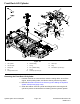
g032283
Figure151
1.LeftPTOmanifold8.Hydraulic90°tting
2.O-ring9.O-ring
3.Quicktting10.O-ring
4.Dustcap
11.O-ring
5.O-ring12.Hydraulic90°tting
6.Hydraulic90°tting13.O-ring
7.O-ring14.Straighttting
1.Ifthettingswereremovedfromthemanifold,dothefollowingsteps:
A.LubricateandinstallnewO-ringswithcleanhydraulicuidontothe
ttings.
B.Toproperlyalignandinstallthettingsintothemanifoldopenings,use
themarksthatyoumadewhentheywereremoved;refertoFigure149,
Figure150,andFigure151forthestraightttinginstallationtorque.
Note:Forinformationontighteningproceduresforadjustablettings;
refertoInstallingtheHydraulicFittings(SAEStraightThreadO-Ring
FittingintotheComponentPort)(page4–12).
2.PositionthePTOcontrolmanifoldtotheframeandattachitwith2bolts
and2angenuts.
3.Removethecapsandplugsfromthettingsandhoses.
4.Connectthehydrauliclinescorrectlytothemanifold;refertoInstallingthe
HydraulicHoseandTube(O-RingFaceSealFitting)(page4–10).
5.Connectthewireharnessconnectortothesolenoidvalve.
6.Ensurethatthehydraulictankisfull.Addthecorrectquantityofuidif
necessary.
Groundsmaster5900TractionUnit
Page4–157
HydraulicSystem:ServiceandRepairs
08159SLRevC