
Service Manual


TractionFlushManifold
g031908
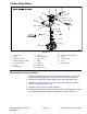
Figure138
1.4-wheeldrivecontrolmanifold
6.Flangenut
11.Hydraulic-uidtemperaturesender
2.O-ring
7.Bulkheadmountplate
12.O-ring
3.O-ring8.Flangenut(2each)13.Flushmanifoldassembly
4.Hydraulicteetting
9.Bolt
14.Flangescrew(4each)
5.Hydraulicteetting10.Bolt(2each)
Note:Theportsonthetractionushmanifoldaremarkedforeasyidenticationof
thecomponents.Example:CVisthecheckvalveportandTSisthetemperature
senderport;refertotheHydraulicSchematicinChapter10—FoldoutDrawings
toidentifythefunctionofthehydrauliclinesandcartridgevalvesateachport.
Note:Thetractionushmanifoldincludesazero-leakNWDplug.Thisplughas
ataperedsealingsurfaceontheplugheadthatisdesignedtoresistvibration
inducedplugloosening.Thezero-leakplugalsohasanO-ringasasecondary
seal.Ifzero-leakplugremovalisnecessary,lightlyraptheplugheadusinga
punchandhammerbeforeusinganallenwrenchtoremovetheplug;theimpact
willallowplugremovalwithlesschanceofdamagetothesocketheadofthe
plug.Wheninstallingtheplug;refertoFigure139forthepluginstallationtorque.
RemovingtheTractionFlushManifold
1.ReadtheGeneralPrecautionsforRemovingandInstallingtheHydraulic
SystemComponents(page4–95).
Groundsmaster5900TractionUnit
Page4–141
HydraulicSystem:ServiceandRepairs
08159SLRevC