
Service Manual


TractionControlManifold
g031902
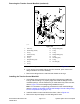
Figure132
1.Tractioncontrolmanifold
4.Planetaryassembly7.Frameassembly
2.Flange-headscrew(4each)5.Leftfrontwheelmotor
8.Brakeassembly
3.FrontPTOcontrolmanifold
6.Frontwheelassembly
Note:Theportsonthetractioncontrolmanifoldaremarkedforeasyidentication
ofthecomponents.Example:PisthepistonpumpconnectionportandSis
thelocationforthesolenoidvalve;refertotheHydraulicSchematicinChapter
10—FoldoutDrawingstoidentifythefunctionofthehydrauliclinesandcartridge
valvesateachport.
RemovingtheTractionControlManifold
1.ReadtheGeneralPrecautionsforRemovingandInstallingtheHydraulic
SystemComponents(page4–95).
2.Cleantheexteriorofthemanifoldandttingsbeforeremovingthemanifoldto
preventcontaminantsfromenteringintothehydraulicsystem.
3.Disconnectthewireharnessconnectorfromthesolenoidvalve.
4.Disconnectallthehydrauliclinesfromthemanifoldandinstallcapsorplugs
ontheopenhydrauliclinesandttingstopreventsystemcontamination.
Labelthedisconnectedhydrauliclinesforproperassembly.
HydraulicSystem:ServiceandRepairs
Page4–130
Groundsmaster5900TractionUnit
08159SLRevC