
Service Manual


Rev. A
Groundsmaster 360 Hydraulic SystemPage 4 − 121
3. If rear steering cylinder is to be removed from ma-
chine, the storage compartment behind operator seat
needs to be removed to allow clearance for cylinder re-
moval. To remove storage compartment, see Storage
Compartment Removal in the Service and Repairs sec-
tion of Chapter 6 − Chassis or, if machine is equipped
with operator cab, see Storage Compartment Removal
in the Service and Repairs section of Chapter 8 − Opera-
tor Cab.
4. Read the General Precautions for Removing and
Installing Hydraulic System Components at the begin-
ning of the Service and Repairs section of this chapter.
WARNING
Before disconnecting or performing any work on
the hydraulic system, all pressure in the system
must be relieved. See Relieving Hydraulic System
Pressure in the General Information section o
f
this chapter
5. Label all hydraulic connections for assembly pur-
poses. Thoroughly clean hydraulic hose ends prior to
disconnecting hoses from the steering cylinder.
6. Disconnect hydraulic hoses from steering cylinder
that is being removed.
7. Put caps or plugs on disconnected hoses and fittings
to prevent contamination.
8. Remove cotter pins (item 14) and slotted hex nuts
(items 15 and 16) that secure steering cylinder to axle.
9. Use appropriate tool to separate steering cylinder
ball joint and rod end from axle assembly. Remove
steering cylinder from machine.
10.If ball joint (item 10) is to be removed from cylinder,
note direction that ball joint is installed in cylinder. Re-
move ball joint from steering cylinder barrel.
11.If necessary, remove rod end (item 12) from steering
cylinder shaft.
12.If necessary, remove fittings from steering cylinder
and discard O−rings.
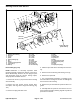
Installation (Fig. 139)
1. If hydraulic fittings were removed from steering cylin-
der, lubricate new O−rings with clean hydraulic oil, posi-
tion O−rings to fittings and install fittings into steering
cylinder ports (see Hydraulic Fitting Installation in the
General Information section of this chapter).
2. If removed, press ball joint (item 10) into barrel and
secure with retaining ring.
3. If rod end (item 141) was removed from steering cyl-
inder shaft, thread rod end into shaft so that distance
from end of shaft to center of grease fitting in rod end is
1.750” (44.5 mm). Torque jam nut from 83 to 101 ft−lb
(113 to 136 N−m). Make sure that distance from end of
shaft to center of grease fitting doesn’t change during
jam nut tightening.
4. Thoroughly clean tapers on ball joint, rod end and
axle assembly bores.
NOTE: Front axle steering cylinder should be installed
so ports are on the upper side. Rear axle steering cylin-
der should be installed so ports are on the lower side.
5. Position steering cylinder to machine.
6. Secure steering cylinder to machine with slotted hex
nuts (items 15 and 16).
A. On front axle steering cylinder, torque rod end
slotted hex nut (item 15) from 57 to 75 ft−lb (78 to
101 N−m). If necessary, continue to tighten hex nut
to allow cotter pin installation.
B. On both front and rear axle steering cylinders,
torque barrel end slotted hex nut (item 16) from 80 to
90 ft−lb (109 to 122 N−m). If necessary, continue to
tighten hex nut to allow cotter pin installation.
C. Install cotter pins to secure hex nuts.
7. Remove caps and plugs from hydraulic hoses and
fittings.
8. Lubricate and install new O−rings on steering cylin-
der fittings. Correctly connect hydraulic hoses to steer-
ing cylinder (see Hydraulic Hose and Tube Installation
in the General Information section of this chapter).
9. Check oil level in hydraulic reservoir and add correct
oil if necessary.
Figure 141
1.750”
(44.5 mm)
END OF SHAFT
ROD END
Hydraulic
System