
Service Manual


Groundsmaster 360Hydraulic System Page 4 − 116
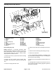
Steering Control Valve
1. Steering wheel
2. Lock nut
3. Flat washer
4. Alignment bushing
5. Steering column assembly
6. Steering control valve
7. Steering plate
8. Carriage screw (4)
9. Mount (4)
10. Washer (4)
11. Flange nut (4)
12. Flange head screw (3)
13. Socket head screw
14. Steering wheel cover
Figure 134
1
2
3
4
6
7
8
9
10
11
12
5
14
Antiseize
Lubricant
20 to 26 ft−lb
(28 to 35 N−m)
13
34 to 42 ft−lb
(47 to 56 N−m)
34 to 42 ft−lb
(47 to 56 N−m)
FRONT
RIGHT
Removal (Fig. 134)
WARNING
Before disconnecting or performing any work on
the hydraulic system, all pressure in the system
must be relieved. See Relieving Hydraulic System
Pressure in the General Information section.
1. Park machine on a level surface, lower cutting deck,
stop engine, engage parking brake and remove key
from the ignition switch.
2. Read the General Precautions for Removing and
Installing Hydraulic System Components at the begin-
ning of the Service and Repairs section of this chapter.
3. Label all hydraulic lines and fittings at steering con-
trol valve for assembly purposes. Note port designa-
tions on steering control valve (Fig. 136). Thoroughly
clean hydraulic connections prior to loosening hydraulic
lines.
4. Disconnect hydraulic lines from steering control
valve. Allow lines to drain into a suitable container.