
Service Manual


Groundsmaster 360Hydraulic System Page 4 − 106
CrossTrax
TM
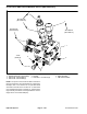
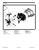
AWD Control Manifold Service (4WD Machines)
1. Pilot directional valve − PD1 & PD2 (2)
2. Orifice 0.040 − OR3 and OR4 (2)
3. Orifice 0.090 − OR1 and OR2 (2)
4. Hex plug
5. Check valve − CV1 and CV2 (2)
6. Relief valve (CRV)
7. AWD control manifold
Figure 128
2
3
6
1
5
4
1
2
30 to 35 ft−lb
(41 to 47 N−m)
30 to 35 ft−lb
(41 to 47 N−m)
25 to 30 ft−lb
(34 to 41 N−m)
7 ft−lb
(9.5 N−m)
7
NOTE: The ports on the CrossTrax AWD control man-
ifold are marked for easy identification of components.
Example: PD1 is the location for the pilot directional
valve PD1 and OR1 is the location for a 0.090 orifice
(see Hydraulic Schematic in Chapter 9 − Foldout Draw-
ings to identify the function of the hydraulic lines and car-
tridge valves at each manifold port).