
Operator's Manual


D.Torquethelocknutsto20to25N∙m(175
to225in-lb).
7.LubricatethegreasettingsonthePTO
driveshaft.
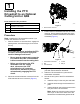
8.Afteryouconnecttheotherendofthedriveshaft
totheattachmentgearboxshaft,connect
thewire-harnessconnectortothePTO
solenoid-valve-coilconnector(Figure3).
2
UsingtheOptional
Cutting-Unit-Mounting
Hardware
Partsneededforthisprocedure:
2Retainerpin
2
Greasetting
2
Washerheadscrew(5/16x7/8inch)
Procedure
Note:Thesecomponentsandprocedurearerequired
onlyifacuttingunitthatrequiresretainerpinsis
mountedtothetractionunit.Refertothecuttingunit
Operator’sManualfortheinstallationinstructions.
Note:Ifyouarenotinstallingacuttingunitonthe
tractionunit,removeortieupthe4deck-liftchains
fromtheliftsuspension.
3
AdjustingtheRollBar
NoPartsRequired
Procedure
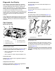
1.Removethe2hairpinsandthe2pinsfromthe
rollbar(Figure5).
2.Raisetherollbartotheuprightpositionand
secureitwiththe2pinsand2hairpins(Figure
5).
Note:Ifyoumustlowertherollbar,pushthebar
forwardtorelievepressureonthepins,remove
thepins,lowerthebarslowly,andsecureitwith
thepinssothatitdoesnotdamagethehood.
g014166
Figure5
1.Rollbar3.Hairpin
2.Pin
4
CheckingtheTirePressure
NoPartsRequired
Procedure
Checkthetirepressure;refertoCheckingtheTire
Pressure(page46).
Important:Maintainpressureinalltiresto
ensureagoodquality-of-cutandpropermachine
performance.Donotunderinatethetires.
5
CheckingtheFluidLevels
NoPartsRequired
Procedure
1.Checkthehydraulic-uidlevelbeforestarting
theengine,refertoCheckingtheHydraulic
System(page51).
2.Checktheengine-oillevelbeforestartingthe
engine,refertoCheckingtheEngine-OilLevel
(page38).
14