
Service Manual


Groundsmaster 360 Hydraulic SystemPage 4 − 91
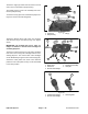
39.Disassemble PTO shaft assembly:
A. Using a bearing puller, remove bearing from PTO
shaft. Discard bearing.
B. Remove spacer from PTO shaft.
C. Slide gear and clutch assembly from PTO shaft.
D. Remove key from PTO shaft slot.
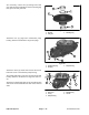
E. Remove two (2) seal rings from PTO shaft
grooves. Discard seal rings.
F. Remove B−plate, C−plate, three (3) A−plates and
three (3) friction plates from PTO shaft.
G. Using a bearing puller, remove bearing from PTO
shaft. Discard bearing.
1. Bearing
2. PTO shaft
3. Spacer
4. Gear
5. Clutch assembly
6. Key
Figure 91
1
6
5
2
3
4
1. Seal ring (2)
2. PTO shaft
3. B−plate
4. C−plate
5. A−plate (3)
6. Friction plate (3)
7. Bearing
Figure 92
1
7
5
2
3
4
5
5
6
6
6
40.Slide three (3) rods from holes in clutch assembly.
41.Slide PTO gear assembly from clutch assembly.
NOTE: Because individual clutch components are not
available, disassembly of the clutch assembly is not
necessary.
1. Rod (3)
2. Clutch assembly
3. PTO gear
Figure 93
1
2
3
Hydraulic
System