
Service Manual


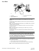


Table Of Contents
- Title Page
- Revision History
- Reader Comments
- Preface
- Table of Contents
- Chapter 1 : Safety
- Chapter 2 : Specifications and Maintenance
- Chapter 3 : Troubleshooting
- Chapter 4 : Engine
- Chapter 5 : Hydraulic System
- General Information
- Hydraulic Schematic
- Hydraulic Flow Diagrams
- Testing the Hydraulic System
- Testing the Traction Circuit - Charge Pressure
- Testing the Wheel Motors Efficiency
- Testing the Traction Circuit - Hydraulic Pump Flow and Relief Pressure
- Testing the Steering Circuit - Steering Control Valve, Relief Valve Pressure and Steering Cylinder
- Testing the Steering Circuit - Charge Pump Flow
- Testing the Auxiliary Control Circuit - Cutting Deck Lift Cylinder Internal Leakage
- Testing the Auxiliary Control Circuit - Hopper Lift Cylinder Internal Leakage
- Testing the Auxiliary Control Circuit - Hopper Tilt Cylinder Internal Leakage
- Testing the Height Of Cut Cylinder Internal Leakage
- Service and Repairs
- General Precautions for Removing and Installing the Hydraulic System Components
- Checking the Hydraulic Lines and Hoses
- Flushing the Hydraulic System
- Filtering the Closed-Loop Traction Circuit
- Priming the Hydraulic Pump
- Charging the Hydraulic System
- Hydraulic Tank
- Auxiliary Control Valve
- Traction Neutral Arm Assembly
- Hydraulic Pump Assembly
- Servicing the Hydraulic Piston Pump
- Servicing the Gear Pump
- Front Wheel Motors
- Rear Wheel Motors
- Servicing the Hydraulic Wheel Motor
- Differential Valve
- Height Of Cut Valve
- Lift Cylinder
- Steering Control Valve
- Steering Cylinder
- Hopper Lift Cylinder
- Hopper Tilt Cylinder
- Height Of Cut Cylinder
- Chute Cleaning Cylinder
- Oil Cooler
- Chapter 6 : Electrical System
- General Information
- Electrical System Quick Checks
- Testing the Electrical Components
- Fuses
- Key Switch
- PTO Switch
- Hazard Light Switch
- Differential Lock Switch
- Radiator Fan Reversal Switch
- Beacon Light Switch
- Indicator Lights
- Height Of Cut Switch
- Seat Switch
- Hour Meter
- Traction Neutral Switch
- Traction Reverse Switch
- Parking Brake Switch
- Oil Pressure Switch
- PTO Electric Clutch
- Fuel Stop Solenoid
- Relays
- Diode Assembly
- Slope Sensor (Optional)
- Service and Repairs
- Chapter 7 : Chassis
- Chapter 8 : Axle and PTO
- Chapter 9 : Hopper Assembly
- Chapter 10 : Cutting Unit
- Appendix A: Foldout Drawings

IndicatorLights
g294708
Figure119
1.Batterychargeindicator
4.Airlterrestrictionindicator
7.Raisedhopperindicator
2.Glowplugindicator
5.Worklightindicator8.Parkingbrakeindicator
3.Oilpressurewarningindicator
6.Roadlightindicator
Theindicatorlightsarelocatedonthedashpanel.
BatteryChargeIndicatorLight
Thebatterychargeindicatorlightshouldilluminatewhenthekeyswitchisinthe
ONpositionwiththeenginenotrunning.Also,itshouldilluminatewhenthe
chargingcircuitisnotworkingproperlywhiletheengineisrunning.
GlowPlugIndicatorLight
Theglowplugindicatorlightshouldilluminatewhenthekeyswitchisplacedin
theONpositionbeforeplacingthekeyswitchintheSTARTposition.
OilPressureWarningIndicatorLight
TheengineoilpressurelightshouldilluminatewhenthekeyswitchisintheON
positionwiththeenginenotrunning.Also,itwillilluminatewhentheengine
oilpressuredropsbelowasafelevel.
IMPORTANT
Iftheoilpressureindicatorlightisilluminatedwiththeengine
running,shutofftheengineimmediately.
ElectricalSystem:TestingtheElectricalComponents
Page6–22
ProLineH800
19241SLRevB