
Operator's Manual


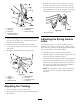
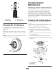


Figure38
1.Speedcontrollever
3.spring
2.Rearpivotspring
AdjustingtheRightSideLinkage
1.Placethespeedcontrolleverintheneutralposition.
2.Placetherightdriveleverinthefullforwardposition.
3.Adjusttherightsidelinkagebyturningthequick
trackknobcounterclockwiseuntilthetirebeginsto
rotateforward(Figure39).
4.Turntheknobclockwise1/4ofaturnatatime.
Thenmovethespeedcontrolforwardandbackto
neutral.Repeatthisuntilrightwheelstopsrotating
forward(Figure39).
5.HoldtheOPCleversdown.
Note:TheOPCleversmustbehelddown
wheneverthespeedcontrolleverisoutoftheneutral
positionortheenginewillkill.
6.Thespringthatkeepstensionontheknobshould
normallynotneedadjustment.Howeverifan
adjustmentisneeded,adjustthelengthofspringto
1inch(26mm)betweenthewashers(Figure39).
7.Adjustspringlengthbyturningnutatfrontofspring
(Figure39).
Figure39
1.Hydrocontrollinkage
3.Spring
2.Quicktrackknob4.1inch(26mm)
AdjustingtheControlRod
CheckingtheControlRod
1.Withrearofmachinestillonjackstandsandengine
runningatfullthrottle,movethespeedcontrollever
tothemediumspeedposition.
Note:TheOPCleversmustbehelddown
wheneverthespeedcontrolleverisoutoftheneutral
positionortheenginewillkill.
2.Movetherespectivedriveleverupwarduntilit
reachestheneutralpositionandengageneutrallocks.
3.Ifthetirerotatesineitherdirection,thelengthofthe
controlrodwillneedtobeadjusted.
AdjustingtheControlRod
1.Adjusttherodlengthbyreleasingthedrivelever
andremovingthehairpincotterpinandclevispin.
Rotatetherodintherodtting(Figure40).
2.Lengthenthecontrolrodifthetireisturningin
reverseandshortentherodifthetireisturning
forward.
3.Rotatetherodseveralturnsifthetireisrotatingfast.
Then,adjusttherodin1/2turnincrements.
4.Placetheclevispinintothedrivelever(Figure40).
35