
Service Manual


MOWER DECK
8-25Fixed Deck Mid-Size Service Manual
8
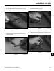
Fig 972 PICT-6204
5. Remove the nut from the bolt securing the adjust-
able baffl e to the underside of the mower deck (Fig.
972).
Fig 971 PICT-6202
4. Remove the lock screw by unthreading it from the
adjustable baffl e assembly (Fig. 971).
Fig 970 PICT-6200a
3. Remove the lock cap (Fig. 970).
Fig 969 PICT-6199
2. Slide the lock lever out of the lock cap (Fig. 969).