
Service Manual


HYDROSTATIC DRIVE SYSTEM
6-19Fixed Deck Mid-Size Service Manual
6
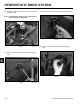
Fig 770 PICT-6680a
9. Install an e-ring onto the drive rod trunnion (Fig.
770).
Fig 772 PICT-6684
11. Install a nut onto the speed control link bolt (Fig.
772).
Fig 771 PICT-6681
10. Insert the bolt on the lower end of the speed control
link into the control shaft (Fig. 771).
Fig 773 PICT-6688
12. Position the 4 bolts, spacers and the hydro control
shield assembly onto the frame (Fig. 773).
Note: The two bottom spacers are approximately
3/8” (.95cm) shorter than the upper spacers.