
Operator's Manual

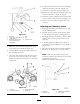


Figure 48
1. 1/2 inch (13 mm)
deection here
4. Locknut
2. Assist arm
5. Turnbuckle
3. Front stop
5. Eng ag e the bladed control lev er (PTO) and
c hec k the belt tension.
6. If there is no adjustment left in the tur nbuc kle
and the belt is still loose , the rear idler pulley
needs to be positioned to the middle or front
hole ( Figure 49 ). Use the hole that will gi v e
the cor rect adjustment.
7. W hen the idler pulley is mo v ed the belt guide
m ust be mo v ed. Mo v e the belt guide to the
front position ( Figure 49 ).
Figure 49
1. Rear idler pulley 4. Belt guide in back position
2. Middle hole 5. Front idler pulley
3. Front hole
8. Chec k the belt guide under the engine frame
for proper adjustment ( Figure 50 ).
Note: T he distance betw een the belt guide
and the mo w er belt should be 3/4 inc h (19 mm)
when y ou eng ag e the mo w er belt ( Figure 50 ).
Adjust the mo w er belt as necessar y . T he
diseng ag ed belt should not drag or fall off the
pulley when the guides are properly adjusted.
Figure 50
1. Belt guide
9. Chec k the blade brak e adjustment; refer to
Adjusting the Blade Brak e .
Adjusting the PTO Engagement
Linkage
T he PTO eng ag ement linkag e adjustment is
located beneath the front left hand cor ner of the
engine dec k.
1. Diseng ag e the blade control (PTO) lev er and
set the parking brak es .
2. Stop the engine and w ait for all mo ving par ts
to stop before lea ving the operating position.
3. Eng ag e the blade control lev er (PTO).
4. Adjust the linkag e length to where the lo w er
end of the bellcrank just clears the axle suppor t
gusset ( Figure 51 ).
41