
Operator's Manual


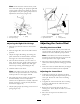


Note: If inconsistent neutral occurs , c hec k
to be sure both springs are properly tightened
on the speed control lev er under the console ,
especially the rear pi v ot spring . R e peat abo v e
adjustments if necessar y ( Figure 38 ).
Figure 38
1. Speed control lever
3. spring
2. Rear pivot spring
Adjusting the Right Side Linkage
1. Place the speed control lev er in the neutral
position.
2. Place the right dri v e lev er in the full forw ard
position.
3. Adjust the right side linkag e b y tur ning the
quic k trac k knob countercloc kwise until the
tire begins to rotate forw ard ( Figure 39 ).
4. T ur n the knob cloc kwise 1/4 of a tur n at a
time . T hen mo v e the speed control forw ard
and bac k to neutral. R e peat this until right
wheel stops rotating forw ard ( Figure 39 ).
5. Hold the OPC lev ers do wn.
Note: T he OPC lev ers m ust be held do wn
whenev er the speed control lev er is out of the
neutral position or the engine will kill.
6. T he spring that k ee ps tension on the knob
should nor mally not need adjustment.
Ho w ev er if an adjustment is needed, adjust the
length of spring to 1 inc h (26 mm) betw een
the w ashers ( Figure 39 ).
7. Adjust spring length b y tur ning n ut at front of
spring ( Figure 39 ).
Figure 39
1. Hydro control linkage
3. Spring
2. Quick track knob
4. 1 inch (26 mm)
Adjusting the Control Rod
Checking the Control Rod
1. With rear of mac hine still on jac k stands and
engine r unning at full throttle , mo v e the speed
control lev er to the medium speed position.
Note: T he OPC lev ers m ust be held do wn
whenev er the speed control lev er is out of the
neutral position or the engine will kill.
2. Mo v e the respecti v e dri v e lev er upw ard until it
reac hes the neutral position and eng ag e neutral
loc ks .
3. If the tire rotates in either direction, the length
of the control rod will need to be adjusted.
Adjusting the Control Rod
1. Adjust the rod length b y releasing the dri v e
lev er and remo ving the hair pin cotter pin and
clevis pin. R otate the rod in the rod fitting
( Figure 40 ).
2. Lengthen the control rod if the tire is tur ning
in rev erse and shor ten the rod if the tire is
tur ning forw ard.
3. R otate the rod sev eral tur ns if the tire is
rotating fast. T hen, adjust the rod in 1/2 tur n
increments .
4. Place the clevis pin into the dri v e lev er
( Figure 40 ).
36