
Operator's Manual


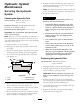

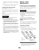


Figure56
1.Bellcrank4.Yoke
2.Safetyswitchlocated
underenginedeck
5.Nut
3.Bellcrankjustclearsthe
gussetwiththePTO
engageded
6.Assistarmlink
5.Makesuretheassistarmisagainsttherearassistarm
stoponthedeck(Figure57).
6.Pushthebladecontrollever(PTO)downtothe
disengagedposition.
7.Theassistarmshouldcontactthefrontassistarm
stoponthedeck.Ifitdoesnotcontact,adjustthe
bellcranksoitisclosertothegusset(
Figure57).
Figure57
1.Yoke5.Assistarmlink
2.Nut6.Assistarm
3.Rearassistarmstop7.Turnbuckle
4.Frontassistarmstop
8.Toadjusttheassistarmlink,removethehairpin
cotterpinfromtheassistarm(Figure57).
9.Loosenthenutagainsttheyoke(Figure56).
10.Removetheassistarmlinkfromtheassistarmand
rotatethelinktoadjustthelength.
11.Installtheassistarmlinkintotheassistarmand
secureitwiththehairpincotterpin(
Figure57).
12.Checkiftheassistarmhitsagainstthestops
correctly.
AdjustingthePTOSafetySwitch
1.Disengagethebladecontrol(PTO)leverandsetthe
parkingbrakes.
2.Stoptheengineandwaitforallmovingpartstostop
beforeleavingtheoperatingposition.
3.Disengagethebladecontrollever(PTO).Makesure
theassistarmisagainstthefrontassiststoparm.
4.Ifneeded,adjustthebladesafetyswitchbyloosening
theboltsholdingtheswitchbracket(
Figure58).
5.Movethemountingbracketuntilthebellcrank
depressestheplungerbya1/4inch(6mm).
6.
Note:Makesurethebellcrankdoesnottouchthe
switchbodyordamagetotheswitchcouldoccur
(Figure58).
Tightentheswitchmountingbracket.
Figure58
1.Bellcrank
3.Switchmountingbracket
2.Boltsandnuts
4.Switchbody
43