
Service Manual


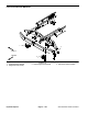


Table Of Contents
- Title Page
- Revision History
- Reader Comments
- Preface
- Table Of Contents
- 1 - Safety
- 2 - Product Records and Maintenance
- 3 - Yanmar Diesel Engine
- 4 - Hydraulic System
- Table of Contents
- Specifications
- General Information
- Hydraulic Schematics
- Hydraulic Flow Diagrams
- Special Tools
- Troubleshooting
- Testing
- Traction Circuit Charge Pressure
- Traction Circuit Relief Pressure
- Reverse Traction Circuit Reducing Valve (PR) Pressure
- Rear Traction Circuit Relief (RV) Pressure
- Piston (Traction) Pump Flow
- Cutting Deck Circuit Pressure
- Cutting Deck Circuit Relief Pressure
- Deck Motor Case Drain Leakage
- Steering Circuit Relief Pressure
- Steering Cylinder Internal Leakage
- Lift/Lower Circuit Relief Pressure
- Engine Cooling Fan Circuit
- Gear Pump Flow
- Adjustments
- Service and Repairs
- General Precautions for Removing and Installing Hydraulic System Components
- Check Hydraulic Lines and Hoses
- Priming Hydraulic Pumps
- Flush Hydraulic System
- Filtering Closed-Loop Traction Circuit
- Charge Hydraulic System
- Gear Pump
- Gear Pump Service
- Piston (Traction) Pump
- Piston (Traction) Pump Service
- Rear Traction Control Manifold
- Rear Traction Control Manifold Service
- Control Manifold Cartridge Valve Service
- HI/LOW Range Control Manifold
- Rear Axle Motor
- Front Wheel Motors
- Rear Axle and Front Wheel Motor Service
- Cutting Deck Motor
- Cutting Deck Motor Service
- Deck Control Manifold
- Deck Control Manifold Service (GM 4500-D)
- Deck Control Manifold Service (GM 4700-D)
- Steering Control Valve
- Steering Control Valve Service
- Steering Cylinder
- Steering Cylinder Service
- Engine Cooling Fan Motor
- Engine Cooling Fan Motor Service
- Fan Control Manifold
- Fan Control Manifold Service
- Lift Control Manifold
- Lift Control Manifold Service (GM 4500-D)
- Lift Control Manifold Service (GM 4700-D)
- Lift Circuit Junction Manifold
- Lift Cylinders: Decks #1, #4 and #5
- Lift Cylinders: Decks #2 and #3
- Lift Cylinders: Decks #6 and #7 (GM 4700-D)
- Lift Cylinder Service
- Hydraulic Reservoir
- Radiator and Oil Cooler Assembly
- 5 - Electrical System
- Table of Contents
- General Information
- Special Tools
- InfoCenter Display
- Troubleshooting
- Electrical System Quick Checks
- Adjustments
- Component Testing
- Ignition Switch
- Fuses
- Fusible Link Harness
- PTO Switch
- Hi/Low Speed, Engine Speed Request and Cutting Deck Lift Switches
- Headlight Switch
- Seat Switch
- Parking Brake Switch
- Cutting Deck Position Switches
- Relays with Four (4) Terminals
- Relays with Five (5) Terminals
- Traction Pedal Position Sensor
- Toro Electronic Controllers (TEC)
- Hydraulic Solenoid Valve Coils
- Piston (Traction) Pump Control Solenoid Coils
- Hydraulic Oil Temperature Sender
- Fuel Pump (Models 30873 and 30874)
- Fuel Pump (Models 30881 and 30882)
- CAN-bus Termination Resistor
- Diode Assemblies
- Resistor Assemblies
- Fan Speed Switch (Machines with Two−Post ROPS Extension Operator Fan Kit)
- Resistor Module (Machines with Two−Post ROPS Extension Operator Fan Kit)
- Service and Repairs
- 6 - Axles, Planetaries and Brakes
- Table of Contents
- Specifications
- General Information
- Adjustments
- Service and Repairs
- Brake Assembly
- Brake Inspection and Repair
- Planetary Drive Assembly
- OPH-2 Series Planetary Drive Service
- VA02 Series Planetary Drive Service
- Rear Axle Assembly
- Rear Axle Service
- Bevel Gear Case and Axle Case
- Differential Shafts
- Axle Shafts
- Input Shaft/Pinion Gear
- Differential Gear
- Pinion Gear to Ring Gear Engagement
- 7 - Chassis
- 8 - Cutting Decks
- 9 - Foldout Drawings
- Electrical Drawing Designations
- Groundsmaster 4500--D Hydraulic Schematic
- Groundsmaster 4500--D With Optional Flow Divider Kit Hydraulic Schematic
- Groundsmaster 4700--D Hydraulic Schematic
- Groundsmaster 4700--D With Optional Flow Divider Kit Hydraulic Schematic
- Electrical Schematic Groundsmaster 4500--D/4700--D Models 30881 and 30882 (Serial numbers below 315000300)
- Electrical Schematic Groundsmaster 4500--D/4700--DModels 30873 and 30874(Serial numbers below 315000300)
- Groundsmaster 4500--D/4700--D Electrical Schematic Models 30881 and 30882 (Serial Numbers 315000301 to 399999999)
- Groundsmaster 4500--D/4700--D Electrical Schematic Models 30873 and 30874 (Serial Numbers 315000301 to 399999999)
- Groundsmaster 4500--D/4700--D Electrical Schematic Models 30881 and 30882(Serial Numbers 400000000 to 403450000)
- Groundsmaster 4500--D/4700--D Electrical Schematic Models 30873 and 30874(Serial Numbers 400000000 to 403450000)
- Groundsmaster 4500--D/4700--D Electrical Schematic (Serial Numbers Serial Numbers 403450001 to 408000000)Models 30881 and 30882
- Groundsmaster 4500--D/4700--DElectrical Schematic(Serial Numbers Above 408000000)
- Groundsmaster 4500--D/4700--D Electrical Schematic (Serial Numbers Above 403450001) Models 30873 and 30874
- Electrical Schematic Groundsmaster 4500--D/4700--D Optional Operator Cab (Serial number below 399999999)
- Groundsmaster 4500--D/4700--D Electrical Schematic Optional Operator Cab (Serial Numbers Above 400000000)
- Groundsmaster 4500--D/4700--D Main Wire Harness (Serial number below 315000300)
- Groundsmaster 4500--D/4700--D Main Wire Harness (Serial Numbers 315000301 to 399999999)
- Groundsmaster 4500--D/4700--D Main Wire Harness (Serial Numbers 400000000 to 403450000)
- Groundsmaster 4500--D/4700--D Main Wire Harness (Serial Numbers Above 403450001)
- Groundsmaster 4500--D/4700--D Seat and Console Wire Harness (Serial number below 399999999)
- Groundsmaster 4500--D/4700--D Seat and Console Wire Harness (Serial Numbers 400000000 to 403450000)
- Groundsmaster 4500--D/4700--D Seat and Console Wire Harness (Serial Numbers Above 403450001)
- Groundsmaster 4500--D/4700--D Power Center Wire Harness(Serial number below 403450000)
- Groundsmaster 4500--D/4700--D Power Center Wire Harness(Serial Numbers Above 403450001)
- Deck 6 and 7 Wire Harness Groundsmaster 4700--D
- (Models 30881 and 30882) Engine Wire Harness Drawing Groundsmaster 4500--D/4700--D (Serial number below 315000000)
- Groundsmaster 4500--D/4700--D (Models 30881 and 30882) Engine Wire Harness Drawing(Serial Numbers 315000001 to 408000000)
- Groundsmaster 4500--D/4700--D(Models 30881 and 30882)Engine Wire Harness Drawing(Serial Numbers Above 408000000)
- Groundsmaster 4500--D/4700--D(Models 30881 and 30882)Engine DPF Sub--Wire Harness Drawing(Serial Numbers Above 408000000)
- (Models 30873 and 30874) Engine Wire Harness Drawing Groundsmaster 4500--D/4700--D
- Groundsmaster 4500--D/4700--D Wire Harness Diagram -- Two--Post ROPS Extension
- Groundsmaster 4500--D/4700--DPower Harness Kit -- Wiring Diagram

Groundsmaster 4500-- D/4700--D Hydraulic SystemPage 4 -- 139
Removal (Fig. 116)
1. Park machine on a level surface, lower cutting
decks, stop engine, engage parking brake and remove
key from the ignition switch.
2. Read the G eneral Precautions for Removing and
Installing Hydraulic System Components at the begin-
ning of the Service and Repairs section of this chapter.
3. To prevent contamination of hydraulic system during
manifold removal, thoroughly clean exterior of manifold.
WARNING
Make sure that cutting decks are fully lowered
before loosening hydraulic lines from lift circuit
junction manifold. If decks are raised as hydrau-
lic lines are loosened, decks may drop unexpect-
edly.
NOTE: Upper three (3) hydraulic hoses on the front of
the junction manifold thread into manifold ports. Loosen
or remove opposite end of these hoses at lift cylinder fit-
tings to allow hose removal from the manifold.
4. Disconnect hydraulic lines from manifold and put
caps or plugs on open hydraulic lines and fittings. Label
disconnected hydraulic lines for proper assembly.
5. Remove hydraulic manifold from the frame using
Figure 116 as guide.
IMPORTANT: A flow control orifice is placed be-
neath several of the hydraulic fittings on the l ift cir-
cuit junction manifold (Fig. 117). The manifold uses
two (2) different orifice sizes. If a fitting is removed
from the lift junction manifold and an orifice is in the
manifold port, make sure to remove orifice and label
its position for assembly purposes. Also note loca-
tion of groove in orifice for assembly purposes.
6. If necessary, remove fittings from manifold and dis-
card O--rings (Figs. 117 and 118).
Installation (Fig. 116)
IMPORTANT: When installing orifice in manifold,
make sure that orifice is flat in the base of the man-
ifold port. Manifold damage is possible if the orifice
is cocked in the cavity.
1. If fittings were removed from junction m anifold, lubri-
cate and place new O--rings onto fittings. Install fittings
into manifold openings making sure that orifice is cor-
rectly placed before threading fitting into manifold. Tight-
en fittings (see Hydraulic Fitting I nstallation in the
General Information section of this chapter). Refer to
Figures 117 and 118 for fitting installation torque.
2. Install hydraulic manifold to the frame using Figure
116 as guide.
3. Remove caps and plugs from fittings and hydraulic
lines. Properly connect hydraulic lines to manifold (see
Hydraulic Hose and Tube Installation in the General In-
formation section of this chapter).
1. Manifold body
2. Orifice (0.055)
3. Orifice (0.030)
4. Straight fitting (3 used)
5. Zero leak plug
Figure 117
25 ft--lb
(34 N--m)
4
3
2
1
5
UP
20 ft--lb
(27 N-- m)
3
FRONT VIEW
1. Manifold body
2. O--ring
3. Straight fitting (3 used)
4. O--ring
5. 90
o
hydraulic fitting
Figure 118
25 ft--lb
(34 N--m)
4
3
2
1
2
4
5
UP
REAR VIEW
Hydraulic
System