
Service Manual


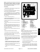


Table Of Contents
- Title Page
- Revision History
- Reader Comments
- Preface
- Table Of Contents
- 1 - Safety
- 2 - Product Records and Maintenance
- 3 - Yanmar Diesel Engine
- 4 - Hydraulic System
- Table of Contents
- Specifications
- General Information
- Hydraulic Schematics
- Hydraulic Flow Diagrams
- Special Tools
- Troubleshooting
- Testing
- Traction Circuit Charge Pressure
- Traction Circuit Relief Pressure
- Reverse Traction Circuit Reducing Valve (PR) Pressure
- Rear Traction Circuit Relief (RV) Pressure
- Piston (Traction) Pump Flow
- Cutting Deck Circuit Pressure
- Cutting Deck Circuit Relief Pressure
- Deck Motor Case Drain Leakage
- Steering Circuit Relief Pressure
- Steering Cylinder Internal Leakage
- Lift/Lower Circuit Relief Pressure
- Engine Cooling Fan Circuit
- Gear Pump Flow
- Adjustments
- Service and Repairs
- General Precautions for Removing and Installing Hydraulic System Components
- Check Hydraulic Lines and Hoses
- Priming Hydraulic Pumps
- Flush Hydraulic System
- Filtering Closed-Loop Traction Circuit
- Charge Hydraulic System
- Gear Pump
- Gear Pump Service
- Piston (Traction) Pump
- Piston (Traction) Pump Service
- Rear Traction Control Manifold
- Rear Traction Control Manifold Service
- Control Manifold Cartridge Valve Service
- HI/LOW Range Control Manifold
- Rear Axle Motor
- Front Wheel Motors
- Rear Axle and Front Wheel Motor Service
- Cutting Deck Motor
- Cutting Deck Motor Service
- Deck Control Manifold
- Deck Control Manifold Service (GM 4500-D)
- Deck Control Manifold Service (GM 4700-D)
- Steering Control Valve
- Steering Control Valve Service
- Steering Cylinder
- Steering Cylinder Service
- Engine Cooling Fan Motor
- Engine Cooling Fan Motor Service
- Fan Control Manifold
- Fan Control Manifold Service
- Lift Control Manifold
- Lift Control Manifold Service (GM 4500-D)
- Lift Control Manifold Service (GM 4700-D)
- Lift Circuit Junction Manifold
- Lift Cylinders: Decks #1, #4 and #5
- Lift Cylinders: Decks #2 and #3
- Lift Cylinders: Decks #6 and #7 (GM 4700-D)
- Lift Cylinder Service
- Hydraulic Reservoir
- Radiator and Oil Cooler Assembly
- 5 - Electrical System
- Table of Contents
- General Information
- Special Tools
- InfoCenter Display
- Troubleshooting
- Electrical System Quick Checks
- Adjustments
- Component Testing
- Ignition Switch
- Fuses
- Fusible Link Harness
- PTO Switch
- Hi/Low Speed, Engine Speed Request and Cutting Deck Lift Switches
- Headlight Switch
- Seat Switch
- Parking Brake Switch
- Cutting Deck Position Switches
- Relays with Four (4) Terminals
- Relays with Five (5) Terminals
- Traction Pedal Position Sensor
- Toro Electronic Controllers (TEC)
- Hydraulic Solenoid Valve Coils
- Piston (Traction) Pump Control Solenoid Coils
- Hydraulic Oil Temperature Sender
- Fuel Pump (Models 30873 and 30874)
- Fuel Pump (Models 30881 and 30882)
- CAN-bus Termination Resistor
- Diode Assemblies
- Resistor Assemblies
- Fan Speed Switch (Machines with Two−Post ROPS Extension Operator Fan Kit)
- Resistor Module (Machines with Two−Post ROPS Extension Operator Fan Kit)
- Service and Repairs
- 6 - Axles, Planetaries and Brakes
- Table of Contents
- Specifications
- General Information
- Adjustments
- Service and Repairs
- Brake Assembly
- Brake Inspection and Repair
- Planetary Drive Assembly
- OPH-2 Series Planetary Drive Service
- VA02 Series Planetary Drive Service
- Rear Axle Assembly
- Rear Axle Service
- Bevel Gear Case and Axle Case
- Differential Shafts
- Axle Shafts
- Input Shaft/Pinion Gear
- Differential Gear
- Pinion Gear to Ring Gear Engagement
- 7 - Chassis
- 8 - Cutting Decks
- 9 - Foldout Drawings
- Electrical Drawing Designations
- Groundsmaster 4500--D Hydraulic Schematic
- Groundsmaster 4500--D With Optional Flow Divider Kit Hydraulic Schematic
- Groundsmaster 4700--D Hydraulic Schematic
- Groundsmaster 4700--D With Optional Flow Divider Kit Hydraulic Schematic
- Electrical Schematic Groundsmaster 4500--D/4700--D Models 30881 and 30882 (Serial numbers below 315000300)
- Electrical Schematic Groundsmaster 4500--D/4700--DModels 30873 and 30874(Serial numbers below 315000300)
- Groundsmaster 4500--D/4700--D Electrical Schematic Models 30881 and 30882 (Serial Numbers 315000301 to 399999999)
- Groundsmaster 4500--D/4700--D Electrical Schematic Models 30873 and 30874 (Serial Numbers 315000301 to 399999999)
- Groundsmaster 4500--D/4700--D Electrical Schematic Models 30881 and 30882(Serial Numbers 400000000 to 403450000)
- Groundsmaster 4500--D/4700--D Electrical Schematic Models 30873 and 30874(Serial Numbers 400000000 to 403450000)
- Groundsmaster 4500--D/4700--D Electrical Schematic (Serial Numbers Serial Numbers 403450001 to 408000000)Models 30881 and 30882
- Groundsmaster 4500--D/4700--DElectrical Schematic(Serial Numbers Above 408000000)
- Groundsmaster 4500--D/4700--D Electrical Schematic (Serial Numbers Above 403450001) Models 30873 and 30874
- Electrical Schematic Groundsmaster 4500--D/4700--D Optional Operator Cab (Serial number below 399999999)
- Groundsmaster 4500--D/4700--D Electrical Schematic Optional Operator Cab (Serial Numbers Above 400000000)
- Groundsmaster 4500--D/4700--D Main Wire Harness (Serial number below 315000300)
- Groundsmaster 4500--D/4700--D Main Wire Harness (Serial Numbers 315000301 to 399999999)
- Groundsmaster 4500--D/4700--D Main Wire Harness (Serial Numbers 400000000 to 403450000)
- Groundsmaster 4500--D/4700--D Main Wire Harness (Serial Numbers Above 403450001)
- Groundsmaster 4500--D/4700--D Seat and Console Wire Harness (Serial number below 399999999)
- Groundsmaster 4500--D/4700--D Seat and Console Wire Harness (Serial Numbers 400000000 to 403450000)
- Groundsmaster 4500--D/4700--D Seat and Console Wire Harness (Serial Numbers Above 403450001)
- Groundsmaster 4500--D/4700--D Power Center Wire Harness(Serial number below 403450000)
- Groundsmaster 4500--D/4700--D Power Center Wire Harness(Serial Numbers Above 403450001)
- Deck 6 and 7 Wire Harness Groundsmaster 4700--D
- (Models 30881 and 30882) Engine Wire Harness Drawing Groundsmaster 4500--D/4700--D (Serial number below 315000000)
- Groundsmaster 4500--D/4700--D (Models 30881 and 30882) Engine Wire Harness Drawing(Serial Numbers 315000001 to 408000000)
- Groundsmaster 4500--D/4700--D(Models 30881 and 30882)Engine Wire Harness Drawing(Serial Numbers Above 408000000)
- Groundsmaster 4500--D/4700--D(Models 30881 and 30882)Engine DPF Sub--Wire Harness Drawing(Serial Numbers Above 408000000)
- (Models 30873 and 30874) Engine Wire Harness Drawing Groundsmaster 4500--D/4700--D
- Groundsmaster 4500--D/4700--D Wire Harness Diagram -- Two--Post ROPS Extension
- Groundsmaster 4500--D/4700--DPower Harness Kit -- Wiring Diagram

Groundsmaster 4500−D/4700−D Page 6 − 17 Axles, Planetaries and Brakes
NOTE: The planetary drive assembly is best serviced
with the planetary installed to machine or the spindle
firmly secured to a fixture or workbench. If the spindle
(item 1) needs to be removed from machine, see Plane-
tary Drive Assembly in this chapter.
Disassembly
1. Park machine on a level surface, stop engine and re-
move key from the ignition switch.
2. Drain oil from planetary drive and brake assembly;
refer to traction unit Operator’s Manual.
3. Chock rear/front wheels and jack up front/rear of
machine (see Jacking Instructions in Chapter 1 − Safe-
ty). Support machine with jack stands and remove rear
wheel assembly.
4. Remove retaining ring (item 16).
5. Remove end cap and thrust plate. Retrieve and dis-
card O−ring from ring gear bore.
6. Remove primary gear and drive shaft assembly
(items 24−26).
7. Remove primary carrier and secondary carrier from
ring gear.
8. Bend the locking washer tab away from the lock nut.
Use a TMFS12 spanner socket to remove the 55 x 1.5
mm lock nut. Remove the locking washer and spacer.
Discard the locking washer.
9. Carefully remove housing and bearing cones from
spindle.
10.Remove and discard seals from housing.
11. If necessary, remove bearing cups from housing.
12.If wheel stud removal is necessary, use a press to re-
move the stud(s) from the housing.
13.If necessary, remove the ring gear from the housing:
NOTE: High strength thread locking compound was
used during assembly. It may be necessary to heat
the ring gear near the mounting screws to release
the screws.
A. Remove socket head screws (item 7) and lock
washers that secure the ring gear to the housing.
B. Remove the ring gear and retrieve the four (4)
dowel pins (item 10) from housing.
C. Remove the O−ring from the housing bore and
discard.
1. Spindle
2. Boot seal
3. Lip seal
4. Inner bearing cup (2)
5. Inner bearing cone (2)
6. Wheel stud (8)
7. Socket head screw (8)
8. Lock washer (8)
9. Housing
10. Dowel pin (4)
11. O−ring
12. Spacer
13. Locking washer
14. Lock nut
15. Ring gear
16. Retaining ring
17. Plug
18. O−ring
19. Plug (2)
20. O−Ring (2)
21. End cap
22. Thrust plate
23. O−Ring
24. Retaining ring (2)
25. Primary gear
26. Drive shaft
27. Primary carrier asm
28. Secondary carrier asm
Figure 10
G248455
11
12
13 14 15
16
17, 18
19, 20
1
2
3
45 6
78
9
10
21
22
23
24
25
2728
26
Assembly
NOTE: Use new seals, O−rings and locking washer
when assembling the planetary drive.
1. Thoroughly clean parts in solvent and dry completely
after cleaning. Inspect parts for damage or excessive
wear and replace as necessary.
2. If any wheel studs were removed, use a press to
install new studs into housing. Make sure that stud
shoulder is fully pressed against housing surface.
3. If ring gear was removed from housing:
A. Fit four (4) dowel pins in housing.
B. Apply a light coat of grease to a new O−ring and
install it in the housing bore.
C. Apply high strength thread locking compound
and secure ring gear to housing with lock washers
and socket head screws. Tighten screws to 27 ft−lb
(37 N−m).
Axles, Planetaries
and Brakes