
Operator's Manual


Engine-SpeedSwitch
Theengine-speedswitch(Figure11)has2modesto
changetheenginespeed.Taptheswitchtoincrease
ordecreasetheenginespeedin100rpmincrements.
HolddowntheswitchtoautomaticallymovetoHigh
orLowidle,dependingonwhichendoftheswitch
youpress.
PTOSwitch
ThePTOswitchhas2positions:OUT(START)and
IN(STOP).PullthePTObuttonouttoengagethe
cutting-unitblades.Pushthebuttonintodisengage
thecutting-unitblades(Figure11).
High-LowSpeedControl
Theswitch(Figure11)allowsthespeedrangeto
increasefortransportingthemachine.T oswitch
betweentheHighandLowspeedranges,raisethe
cuttingunits,disengagethePTOandthecruise
control,putthetractionpedalintotheNEUTRAL
position,andmovethemachineataslowspeed.
Note:Thecuttingunitsdonotoperateand/orcannot
beloweredfromthetransportpositionwhenthe
switchisinthehighrange.
Cruise-ControlSwitch
Thecruise-controlswitchlocksinthepedalposition
tomaintainthedesiredgroundspeed(Figure11).
Pressingtherearoftheswitchturnsoffthecruise
control,themiddlepositionoftheswitchenablesthe
cruise-controlfunction,andthefrontoftheswitchsets
thedesiredgroundspeed.
Note:Pressingeitherbrakepedalormovingthe
tractionpedalintothereverseposition,for1second,
alsodisengagesthepedalposition.
LiftSwitches
Theliftswitchesraiseandlowerthecuttingunits
(Figure11).Presstheswitchesforwardtolowerthe
cuttingunitsandrearwardtoraisethecuttingunits.
Whenstartingthemachine,withthecuttingunitsin
thedownposition,presstheliftswitchdowntoallow
thecuttingunitstooatandmow.
Note:Thecuttingunitsdonotlowerwhileinthe
high-speedrangeandtheydonotraiseorlowerifyou
areoutoftheseatwhiletheengineisrunning.Also,
thecuttingunitslowerwiththekeyintheONposition
andyouareintheseat.
LightSwitch
Pressthelightswitchupwardtoturnthelightstothe
ONposition(Figure11).
Pressthelightswitchdownwardtoturnthelightsto
theOFFposition.
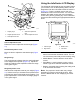
PowerPoint
Usethepowerpoint(Figure13)topoweroptional
12Velectricalaccessories.
g036845
Figure13
1.Powerpoint2.Bagholder
BagHolder
Usethebagholderforstorage(Figure13).
SeatAdjustments
Seat-AdjustmentLever
Movetheseatadjustmentleveronthesideofthe
seatoutward,slidetheseattothedesiredposition,
andreleasethelevertolocktheseatintoposition
(Figure14).
17