
Service Manual


Groundsmaster 4500−D/4700−DPage 5 − 40Electrical System
Toro Electronic Controllers (TEC)
Groundsmaster 4500−D and 4700−D machines use a
Toro Electronic Controller (TEC−5002) to control electri-
cal system operation. Groundsmaster 4700−D ma-
chines use an additional TEC−5001 controller for
electrical control of the rear cutting decks (PTO and lift/
lower functions). The controllers are microprocessor
controlled that sense the condition of various switches
and sensors (inputs). The controllers then direct electri-
cal power to control appropriate machine functions (out-
puts) based on the input state. The controllers are
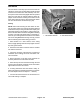
attached to a bracket under the operator seat (Fig. 47).
Logic power is provided to the controllers as long as the
battery cables are connected to the battery. A pair of 2
amp fuses (D−1 for TEC−5002 and D−2 for TEC−5001)
provide circuit protection for this logic power to the con-
trollers.
The TEC−5002 controller monitors the states of the fol-
lowing components as inputs: ignition switch, traction
pedal position sensor, parking brake switch, HI/LOW
speed switch, seat switch, engine speed switch, PTO
switch, center cutting deck lift switch, cutting deck posi-
tion switches (decks 4 and 5), hydraulic temperature
sender and hydraulic pressure transducer.
The TEC−5002 controller controls electrical output to
the engine electronic control unit (ECU) (start and run
functions), fan drive solenoid coils (direction and
speed), traction (piston) pump solenoids (forward and
reverse), traction solenoid coil (HI/LOW speed), PTO
solenoid coils (decks 1 through 5), center cutting decks
raise/lower/float (decks 1 through 5) and counterbal-
ance. Circuit protection for front TEC outputs is provided
by three (3) 7.5 amp fuses (A−1, B−1 and C−1).
On Groundsmaster 4700−D machines, the TEC−5001
controller monitors the states of the following compo-
nents as inputs: ignition switch, cutting deck lift switches
(decks 6 and 7) and cutting deck position switches
(decks 6 and 7).
The TEC−5001 controller controls electrical output to
the PTO solenoid coils (decks 6 and 7), cutting decks
raise/lower/float (decks 6and 7). Circuit protection for
rear TEC outputs is provided by three (3) 7.5 amp fuses
(A−2, B−2 and C−2).
The InfoCenter display should be used to check inputs
and outputs of the TEC controllers. Information on using
the InfoCenter is included in the InfoCenter Display sec-
tion of this chapter.
1. TEC−5002 controller 2. TEC−5001 controller
Figure 47
1
2
Figure 48
12V POWER
(7.5A FUSES)
12V LOGIC
IGNITION
SWITCH
INPUTS
DIGITAL
INPUTS
(OPEN/
ANALOG
INPUTS
POWER
(2 AMP FUSE)
COMM
PORT
CAN BUS
CLOSED)
OUTPUTS
(PWR 2)
GROUND
(VARIABLE)
OUTPUTS
(PWR 3)
OUTPUTS
(PWR 4)
+5 VOLTAGE
OUT
TEC−5002