
Installation Instructions


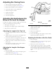


Figure2
1.Adjustmentboltagainsttheframe
5.Tightentheboltandnutsecuringthebumpertothe
frame.
6.Repeatthisprocedurefortheotherbumperonthe
othersideofthemachine.
AssemblingtheCarrierFrame
1.Blockthecastor-wheelassemblyinanuprightposition
usingjackstandsunderthecarrier-framecrossbar
(Figure3).
Figure3
1.Carrier-framecrossbar3.Castor-wheelassembly
(wheelsnotshown)
2.Pivotpin4.Locknutandwasher
2.Lowerthecarrier-framecrossbarintothetopofthe
wheelassemblyandsecureitwithapivotpin,washer,
andlocknut(Figure3).
3.PumpNo.2lithiumgreaseintothettingsoneach
endofthepinuntilgreasestartstocomeoutofthe
bearings.
InstallingtheCarrierFrame
1.Raisetherollbaronthemachineandinstallapinto
secureitononly1sideoftherollbar.
2.Ontheothersideoftherollbar,installaboltandnut
suppliedinthekitintotheholesinsteadofthepin
(Figure4).
Figure4
1.Pivotboltandtabbed
washer
3.Tabbedpin
2.Nut4.Boltreplacingthe
removablerollbarpin
3.Ontheleftsideofthemachine,loosentheclampon
thevent-linehoseandslidethehosedownthemetal
tube(Figure8).Tightentheclamp.
Note:Thisallowsyoutoinstallthecarrierframe
withoutitcontactingthehose.
Figure5
1.Metaltube3.Hose
2.Clamp
4.Removethepivotbolt,tabbedwasher,andnutfrom
therollbar;installthetabbedwasherandpivotbolt
fromtheinsideofthebar,butdonotinstallthenut
yet(Figure4).
4