
Operator's Manual


g031692
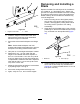
Figure95
1.Height-of-cutbracket2.Shims
3.Installtheheight-of-cutbrackettothedeck
framewiththeremainingshimsassembled
belowtheheight-of-cutbracket.
4.Securethesocket-headbolt/spacerandange
nut.
Note:Socket-headbolt/spacerareheld
togetherwiththread-lockingadhesivetoprevent
thespacerfromfallinginsidethedeckframe.
5.Verifythe12o’clockheightandadjustifneeded.
6.Determineifonly1orboth(rightandleft)
height-of-cutbracketsneedtobeadjusted.If
the3or9o’clocksideis1.6to6.0mm(0.06to
0.24inch)higherthanthenewfrontheightthen
noadjustmentisneededforthatside.Adjustthe
othersidetowithin1.6to6.0mm(0.06to0.24
inch)ofthecorrectside.
7.Adjusttherightand/orleftheight-of-cutbrackets
byrepeatingsteps1through3.
8.Securethecarriageboltsandangenuts.
9.Again,verifythe12,3,and9o’clockheights.
RemovingandInstallinga
Blade
Replacethebladeifasolidobjectishit,thebladeis
outofbalance,orifthebladeisbent.Alwaysuse
genuineT ororeplacementbladestobesureofsafety
andoptimumperformance.Neverusereplacement
bladesmadebyothermanufacturersbecausethey
couldbedangerous.
1.Raisethecuttingdecktothehighestposition,
turnthekeyintheignitionswitchtotheOFF
position,andengagetheparkingbrake.Block
thecuttingdecktopreventitfromfalling
accidentally.
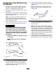
2.Grasptheendofthebladeusingaragorthickly
paddedglove.Removethebladebolt,anti-scalp
cup,andbladefromthespindleshaft(Figure
96).
g011355
Figure96
1.Bladebolt2.Anti-scalpcup
3.Installtheblade,sailfacingtowardthecutting
deck,withtheanti-scalpcupandbladebolt
(Figure96).Tightenthebladeboltto115to149
N∙m(85to110ft-lb).
66