
Service Manual


Groundsmaster 4300--D Hydraulic SystemPage 4 -- 37
4. Raise and support operator seat to allow access to
hydraulic pump assembly.
5. Thoroughly clean ends of hydraulic tubes that con-
nect to the oil filter (Fig. 37). Disconnect hydraulic tubes
from oil filter adapter. Remove two (2) flange head
screwsthatsecureoil filter adapter toframe and remove
oil filter and adapter assembly from machine.
6. Install tee fitting with 1000 PSI (70 bar) pressure
gauge in place of the removed hydraulic filter assembly.
7. Make sure that traction pedal is in neutral, the steer-
ing wheel is stationary and parking brake is engaged.
8. Startengine and run at idle speed. Check for any hy-
draulic leakage from test connections and correct be-
fore proceeding with test.
9. Place throttle to full speed (3200 RPM) and monitor
pressure gauge on tester.
GAUGEREADINGTOBEapproximately 200 to
250 PSI (13.8 to 17.2 bar)
10.Next, determine charge pressure under traction load
byoperatingthemachineinadirect forward and reverse
direction (not steering). Make sure that engine is run-
ning at full speed (3200 RPM). Apply the brakes and
pressthetractionpedal in theforwarddirection and then
to reverse while monitoring the pressure gauge. Stop
engine and record test results.
GAUGEREADINGTOBEapproximately 150 to
250 PSI (13.8 to 17.2 bar)
11.Compare measured charge pressure from step 9
with pressure from step 10:
A. If charge pressure is good under no load (step 9),
but drops below specification w hen under traction
load (step 10), the piston pump should be suspected
of wear and inefficiency. When the pump is worn or
damaged, the charge system is not able to replenish
losttractioncircuitoil due toexcessiveleakage inthe
worn pump.
B. If there is no charge pressure, or pressure is low,
check for restriction in gear pump intake line. Inspect
charge relief valve and valve seat in the traction
pump(see TractionPumpServicein the Serviceand
Repairs section of this chapter). Also, consider a
worn or damaged gear pump (P3) (see Gear Pump
(P3) Flow Test in this section).
NOTE: If gear pump (P3) is worn or damaged, both
charge circuit and steering circuit will be affected.
12.After charge pressure testing is completed, make
sure that engine is not running and then relieve hydrau-
lic system pressure (See Relieving Hydraulic System
Pressure in the General Information section of this
chapter). Remove pressure gauge and tee fitting from
hydraulic tubes. Install oil filter to machine.
13.Lower and secure operator seat.
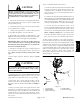
1. Hydraulic tube
2. Oil filter / filter adapter
3. Hydraulic tube
Figure 37
1
3
2
1. Traction pump
2. Plug
3. O--ring
4. Shim kit
5. Spring
6. Charge relief poppet
Figure 38
2
3
1
FRONT
RIGHT
4
5
6
Hydraulic
System