
Service Manual


Groundsmaster 4300--DPage 5 -- 8Electrical System
Diagnostic Display
Groundsmaster 4300--D machines are equipped with a
TEC controller which controls machine electrical func-
tions. The controller monitors various input switches
(e.g. ignition switch, s eat switch, etc.) and energizes
outputs to actuate solenoids or relays for the requested
machine function.
For the controller to control the machine as desired,
each of the input switches, output solenoids and relays
must be connected and functioning properly.
The Diagnostic Display (see Special Tools in this chap-
ter)isatoolto helpthetechnicianverifycorrectelectrical
functions of the machine.
IMPORTANT: The Diagnostic Display must not be
left connected to the machine. It is not designed to
withstand the environment of the machine’s every
dayuse.When use of theDiagnosticDisplayiscom-
pleted, disconnect it from the machine and recon-
nect loopback connector to harness connector. The
machine will not operate without the loopback con-
nector installed on the harness. Store the Diagnos-
tic Display in a dry, secure, indoor location, not on
machine.
Verify Diagnostic Display Input Functions
CAUTION
The interlock switches are for t he protection of
the operator and bystanders and to ensure cor-
rect operation of the machine. Do not bypass or
disconnect switches. Check the operation of the
interlockswitchesdailyforproperoperation.Re-
place any malfunctioning switches before oper-
ating the machine.
1. Park machine on a level surface, lower the cutting
decks, stop the engine and engage the parking brake.
2. Open control panel cover. Locate wire harness and
connectors near TEC controller. Carefully unplug loop-
back connector from harness connector (Fig. 9).
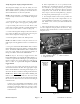
3. ConnecttheDiagnosticDisplayconnectortothehar-
ness connector (Fig. 10). Make surecorrect overlay de-
cal is positioned on the Diagnostic Display (Fig. 11).
4. Turn the ignition switch to the RUN position, but do
not start machine.
NOTE: The red text on the overlay decal refers to con-
troller inputs and the green text refers to controller out-
puts.
1. TEC controller location
2. Loopback connector
3. Harness connector
Figure 9
1
2
3
1. Diagnostic display 2. Loopback connector
Figure 10
1
2
Figure 11
OVERLAY
DIAGNOSTIC
DISPLAY
117--0171