
Service Manual

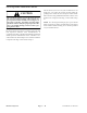


Table Of Contents
- Title Page
- Revision History
- Reader Comments
- Preface
- Table of Contents
- 1 - Safety
- 2 - Product Records and Maintenance
- 3 - Kubota Diesel Engine
- 4 - Hydraulic System
- Specifications
- General Information
- Hydraulic Schematic
- Hydraulic Flow Diagrams
- Special Tools
- Troubleshooting
- Testing
- Traction Circuit Relief Valve (R3) and (R4) Pressure Test
- Traction Circuit Charge Pressure Test
- Gear Pump (P3) Flow Test
- Front Wheel Motor Efficiency Test
- Piston (Traction) Pump Flow Test
- Relief Valve (PRV1) and (PRV2) Pressure Test
- Gear Pump (P1) and (P2) Flow Test
- Deck Motor Efficiency Test
- Lift Relief Valve (PRV) Pressure Test
- Gear Pump (P4) Flow Test
- Lift Cylinder Internal Leakage Test
- Steering Relief Valve (R10) Pressure Test
- Steering Cylinder Internal Leakage Test
- Service and Repairs
- General Precautions for Removing and Installing Hydraulic System Components
- Check Hydraulic Lines and Hoses
- Flush Hydraulic System
- Filtering Closed--Loop Traction Circuit
- Hydraulic System Start--up
- Hydraulic Reservoir
- Hydraulic Pump Drive Shaft
- Hydraulic Pump Assembly
- Piston (Traction) Pump Service
- Gear Pump Service
- Front Wheel Motors
- Rear Wheel Motors
- Wheel Motor Service
- CrossTrax AWD Manifold
- CrossTrax AWD Manifold Service
- Deck Control Manifold
- Deck Control Manifold Service
- Cutting Deck Motor
- Cutting Deck Motor Service
- Lift Control Manifold
- Lift Control Manifold Service
- Lift Cylinder
- Lift Cylinder Service
- Steering Control Valve
- Steering Control Valve Service
- Steering Cylinder
- Steering Cylinder Service
- Oil Cooler
- 5 - Electrical System
- General Information
- Special Tools
- Troubleshooting
- Electrical System Quick Checks
- Adjustments
- Component Testing
- Ignition Switch
- Indicator Lights
- Hour Meter
- Temperature Gauge
- PTO Switch
- Headlight Switch
- Seat Switch
- Joystick Raise and Lower Switches
- Traction Neutral Switch
- Parking Brake Switch
- Mow/Transport Switch
- Start Relay
- Main Power and Glow Relays
- Toro Electronic Controller (TEC)
- Fuses
- Diode Assembly
- Fusible Link Harness
- Hydraulic Solenoid Valve Coil
- Temperature Sender
- High Temperature Shutdown Switch
- Oil Pressure Switch
- Fuel Stop Solenoid
- Fuel Pump
- Service and Repairs
- 6 - Chassis
- 7 - Cutting Decks
- 8 - Foldout Drawings
- Hydraulic Schematic
- Electrical Schematic Sheet 1 of 2 (Serial numbers below 315000000)
- Electrical Schematic Sheet 2 of 2 (Serial numbers below 315000000)
- Eclectrical Schematic (Serial numbers 315000001 to 403430000)
- Eclectrical Schematic (Serial numbers above 403430001)
- Main Wire Harness Drawing (Serial numbers below 315000000)
- Main Wire Harness Diagram (Serial numbers below 315000000)
- Main Wiring Harness Drawing (Serial numbers 315000001 to 403430000)
- Main Wiring Harness Diagram (Serial numbers 315000001 to 403430000)
- Main Wiring Harness Drawing (Serial numbers 403430001 to 405699999)
- Main Wiring Harness Diagram (Serial numbers 403430001 to 405699999)
- Main Wiring Harness Drawing (Serial numbers above 405700000)
- Main Wiring Harness Diagram (Serial numbers above 405700000)
- Seat Wire Harness Drawing
- Seat Wire Harness Diagram
- Engine Wire Harness Drawing
- Engine Wire Harness Diagram

Groundsmaster 4300--D Page 5 -- 25 Electrical System
PTO Switch
The PTO switch is mounted on the control panel and al-
lows the cutting decks to operate when the front of the
switch is depressed. An indicator light on the switch
identifies when the PTO switch is engaged.
The TEC controller monitors the position of the PTO
switch (up or down). Using inputs from the PTO switch
andotherswitchesinthe interlock system, thecontroller
controls the energizing of the hydraulic solenoid valves
used to drive the cutting deck motors.
NOTE: To engage the PTO, the seat has to be occu-
pied, the mow speed limiter has to be in the mow posi-
tion and the cutting decks have to be fully lowered.
Testing
1. Before disconnecting the PTO switch for testing, the
switch and its circuit wiring should be tested as a TEC
controller input with the Diagnostic Display (see Diag-
nostic Display in the Troubleshooting section of this
chapter). If the Diagnostic Display verifies that the PTO
switchandcircuit wiring arefunctioningcorrectly, nofur-
ther switch testing is necessary. If, however, the Diag-
nostic Display determines that the PTO switch and
circuit wiring are not functioning correctly, proceed with
test procedure.
2. Remove control arm covers to gain access to PTO
switch(seeControlArmDisassemblyinthe Service and
Repairs section of Chapter 6 -- Chassis).
3. Make sure ignition switch is in the OFF position. Dis-
connect wire harness electrical connector from the PTO
switch.
4. With the use of a multimeter (ohms setting), the
switch functions may be tested to determine whether
continuity exists between the various terminals for each
switch position. The PTO switch terminals are marked
as shown in Figure 24. The circuitry of this switch is
shown in the chart below. Verify continuity between
switch terminals.
SWITCH
POSITION
NORMAL
CIRCUITS
OTHER
CIRCUITS
ON 2+3 5+6
OFF 2+1 5+4
5. Replace PTO switch if necessary.
6. If PTO switch tests correctly and circuit problem still
exists, check wire harness (see Electrical Schematic
and Circuit Drawings in Chapter 8 -- Foldout Drawings).
7. Connect wire harness electrical connector to the
PTO switch.
8. Install control arm cover to machine (see Control
Arm Assembly in the Service and Repairs section of
Chapter 6 -- Chassis).
1. PTO switch
Figure 23
1
Figure 24
BACK OF SWITCH
NOTE: PTO switch terminals 7 and 8 are for the switch
indicator light. Switch terminals 1, 4, 5 and 6 are not
used on Groundsmaster 4300 --D machines.
Electrical
System