
Service Manual

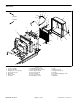


Table Of Contents
- Title Page
- Revision History
- Reader Comments
- Preface
- Table of Contents
- 1 - Safety
- 2 - Product Records and Maintenance
- 3 - Kubota Diesel Engine
- 4 - Hydraulic System
- Specifications
- General Information
- Hydraulic Schematic
- Hydraulic Flow Diagrams
- Special Tools
- Troubleshooting
- Testing
- Traction Circuit Relief Valve (R3) and (R4) Pressure Test
- Traction Circuit Charge Pressure Test
- Gear Pump (P3) Flow Test
- Front Wheel Motor Efficiency Test
- Piston (Traction) Pump Flow Test
- Relief Valve (PRV1) and (PRV2) Pressure Test
- Gear Pump (P1) and (P2) Flow Test
- Deck Motor Efficiency Test
- Lift Relief Valve (PRV) Pressure Test
- Gear Pump (P4) Flow Test
- Lift Cylinder Internal Leakage Test
- Steering Relief Valve (R10) Pressure Test
- Steering Cylinder Internal Leakage Test
- Service and Repairs
- General Precautions for Removing and Installing Hydraulic System Components
- Check Hydraulic Lines and Hoses
- Flush Hydraulic System
- Filtering Closed--Loop Traction Circuit
- Hydraulic System Start--up
- Hydraulic Reservoir
- Hydraulic Pump Drive Shaft
- Hydraulic Pump Assembly
- Piston (Traction) Pump Service
- Gear Pump Service
- Front Wheel Motors
- Rear Wheel Motors
- Wheel Motor Service
- CrossTrax AWD Manifold
- CrossTrax AWD Manifold Service
- Deck Control Manifold
- Deck Control Manifold Service
- Cutting Deck Motor
- Cutting Deck Motor Service
- Lift Control Manifold
- Lift Control Manifold Service
- Lift Cylinder
- Lift Cylinder Service
- Steering Control Valve
- Steering Control Valve Service
- Steering Cylinder
- Steering Cylinder Service
- Oil Cooler
- 5 - Electrical System
- General Information
- Special Tools
- Troubleshooting
- Electrical System Quick Checks
- Adjustments
- Component Testing
- Ignition Switch
- Indicator Lights
- Hour Meter
- Temperature Gauge
- PTO Switch
- Headlight Switch
- Seat Switch
- Joystick Raise and Lower Switches
- Traction Neutral Switch
- Parking Brake Switch
- Mow/Transport Switch
- Start Relay
- Main Power and Glow Relays
- Toro Electronic Controller (TEC)
- Fuses
- Diode Assembly
- Fusible Link Harness
- Hydraulic Solenoid Valve Coil
- Temperature Sender
- High Temperature Shutdown Switch
- Oil Pressure Switch
- Fuel Stop Solenoid
- Fuel Pump
- Service and Repairs
- 6 - Chassis
- 7 - Cutting Decks
- 8 - Foldout Drawings
- Hydraulic Schematic
- Electrical Schematic Sheet 1 of 2 (Serial numbers below 315000000)
- Electrical Schematic Sheet 2 of 2 (Serial numbers below 315000000)
- Eclectrical Schematic (Serial numbers 315000001 to 403430000)
- Eclectrical Schematic (Serial numbers above 403430001)
- Main Wire Harness Drawing (Serial numbers below 315000000)
- Main Wire Harness Diagram (Serial numbers below 315000000)
- Main Wiring Harness Drawing (Serial numbers 315000001 to 403430000)
- Main Wiring Harness Diagram (Serial numbers 315000001 to 403430000)
- Main Wiring Harness Drawing (Serial numbers 403430001 to 405699999)
- Main Wiring Harness Diagram (Serial numbers 403430001 to 405699999)
- Main Wiring Harness Drawing (Serial numbers above 405700000)
- Main Wiring Harness Diagram (Serial numbers above 405700000)
- Seat Wire Harness Drawing
- Seat Wire Harness Diagram
- Engine Wire Harness Drawing
- Engine Wire Harness Diagram

Groundsmaster 4300--D Hydraulic SystemPage 4 -- 115
Inspection
CAUTION
Use eye protection such as goggles when using
compressed air.
1. Wash all cylinder components in solvent. Dry parts
with compressed air.
2. Inspect internal surface of barrel for deep scratches,
out--of--roundness and bending.
3. Inspect head, shaft and piston for excessive pitting,
scoring and wear.
4. Replace steering cylinder if internal components are
found to be worn or damaged.
Assembly (Fig. 103)
1. Use a new seal kit to replace all seals, O--rings and
wear ring to piston and heads. Apply clean hydraulic oil
to all seal kit components before installing.
2. Install front head (item 3) with new seals onto front
shaft (item 1) being careful to not damage head seals
during installation.
IMPORTANT:Make sure to not damage O--ring (item
7) as piston is installed over roll pin hole in front
shaft.
3. Installpiston (item 9) withnew seal,O--ring and wear
ring onto front shaft.
IMPORTANT:When installing roll pin into front and
rear shafts, make sure that shaft surfaces are not
damaged.
4. Sliderear shaftinto frontshaftand alignroll pinholes
in shafts. Install new roll pin to secure shafts.
IMPORTANT: Prevent damage when clamping the
cylinder’s barrel into a vise; clamp on the clevis
only. Do not close vise on barrel.
5. Mount steering cylinder barrel in a vise equipped
with soft jaws by clamping on the barrel clevis.
6. Coat all internal cylinder components with clean hy-
draulicoil.Slideshaftassemblyintobarrel,beingcareful
to not damage seals during installation.
7. Insert rear head with new seals into the barrel being
careful to not damage head seals during installation.
8. Secure front and rear heads in barrel with external
collars. Tighten collars with spanner wrench.
Hydraulic
System