
Service Manual

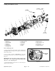


Table Of Contents
- Title Page
- Revision History
- Reader Comments
- Preface
- Table of Contents
- 1 - Safety
- 2 - Product Records and Maintenance
- 3 - Kubota Diesel Engine
- 4 - Hydraulic System
- Specifications
- General Information
- Hydraulic Schematic
- Hydraulic Flow Diagrams
- Special Tools
- Troubleshooting
- Testing
- Traction Circuit Relief Valve (R3) and (R4) Pressure Test
- Traction Circuit Charge Pressure Test
- Gear Pump (P3) Flow Test
- Front Wheel Motor Efficiency Test
- Piston (Traction) Pump Flow Test
- Relief Valve (PRV1) and (PRV2) Pressure Test
- Gear Pump (P1) and (P2) Flow Test
- Deck Motor Efficiency Test
- Lift Relief Valve (PRV) Pressure Test
- Gear Pump (P4) Flow Test
- Lift Cylinder Internal Leakage Test
- Steering Relief Valve (R10) Pressure Test
- Steering Cylinder Internal Leakage Test
- Service and Repairs
- General Precautions for Removing and Installing Hydraulic System Components
- Check Hydraulic Lines and Hoses
- Flush Hydraulic System
- Filtering Closed--Loop Traction Circuit
- Hydraulic System Start--up
- Hydraulic Reservoir
- Hydraulic Pump Drive Shaft
- Hydraulic Pump Assembly
- Piston (Traction) Pump Service
- Gear Pump Service
- Front Wheel Motors
- Rear Wheel Motors
- Wheel Motor Service
- CrossTrax AWD Manifold
- CrossTrax AWD Manifold Service
- Deck Control Manifold
- Deck Control Manifold Service
- Cutting Deck Motor
- Cutting Deck Motor Service
- Lift Control Manifold
- Lift Control Manifold Service
- Lift Cylinder
- Lift Cylinder Service
- Steering Control Valve
- Steering Control Valve Service
- Steering Cylinder
- Steering Cylinder Service
- Oil Cooler
- 5 - Electrical System
- General Information
- Special Tools
- Troubleshooting
- Electrical System Quick Checks
- Adjustments
- Component Testing
- Ignition Switch
- Indicator Lights
- Hour Meter
- Temperature Gauge
- PTO Switch
- Headlight Switch
- Seat Switch
- Joystick Raise and Lower Switches
- Traction Neutral Switch
- Parking Brake Switch
- Mow/Transport Switch
- Start Relay
- Main Power and Glow Relays
- Toro Electronic Controller (TEC)
- Fuses
- Diode Assembly
- Fusible Link Harness
- Hydraulic Solenoid Valve Coil
- Temperature Sender
- High Temperature Shutdown Switch
- Oil Pressure Switch
- Fuel Stop Solenoid
- Fuel Pump
- Service and Repairs
- 6 - Chassis
- 7 - Cutting Decks
- 8 - Foldout Drawings
- Hydraulic Schematic
- Electrical Schematic Sheet 1 of 2 (Serial numbers below 315000000)
- Electrical Schematic Sheet 2 of 2 (Serial numbers below 315000000)
- Eclectrical Schematic (Serial numbers 315000001 to 403430000)
- Eclectrical Schematic (Serial numbers above 403430001)
- Main Wire Harness Drawing (Serial numbers below 315000000)
- Main Wire Harness Diagram (Serial numbers below 315000000)
- Main Wiring Harness Drawing (Serial numbers 315000001 to 403430000)
- Main Wiring Harness Diagram (Serial numbers 315000001 to 403430000)
- Main Wiring Harness Drawing (Serial numbers 403430001 to 405699999)
- Main Wiring Harness Diagram (Serial numbers 403430001 to 405699999)
- Main Wiring Harness Drawing (Serial numbers above 405700000)
- Main Wiring Harness Diagram (Serial numbers above 405700000)
- Seat Wire Harness Drawing
- Seat Wire Harness Diagram
- Engine Wire Harness Drawing
- Engine Wire Harness Diagram

Groundsmaster 4300--DHydraulic System Page 4 -- 104
Lift Cylinder
1. Lift cylinder
2. Pivot shaft
3. Flange head screw
4. Lift arm (#1 shown)
5. Flat washer
6. Hydraulic hose
7. O--ring
8. 90
o
hydraulic fitting
9. O--ring
10. Hydraulic hose
11. Retaining ring
12. Thrust washer
13. Cylinder slide pin
Figure 93
FRONT
RIGHT
1
2
5
3
4
67 to 83 ft--lb
(91 to 112 N--m)
10
11
12
13
11
12
6
7
8
9
NOTE: The procedure for lift cylinder removal and
installation is the same for all Groundsmaster 4300--D
lift cylinders. Figure 93 shows the center, front (deck #1)
lift cylinder.
Removal (Fig. 93)
1. Park the machine on a level surface, engage the
parking brake, lower the cutting decks and stop the en-
gine. Remove the key from the ignition switch.
2. Read the General Precautions for Removing and
Installing Hydraulic System Components at the begin-
ning of the Service and Repairs section of this chapter.
Figure 94
FRONT
#4 #1 #5
#3#2
GROUNDSMASTER
4300--D CUTTING
DECK LOCATIONS