
Service Manual
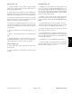


Table Of Contents
- Title Page
- Revision History
- Reader Comments
- Preface
- Table of Contents
- 1 - Safety
- 2 - Product Records and Maintenance
- 3 - Kubota Diesel Engine
- 4 - Hydraulic System
- Specifications
- General Information
- Hydraulic Schematic
- Hydraulic Flow Diagrams
- Special Tools
- Troubleshooting
- Testing
- Traction Circuit Relief Valve (R3) and (R4) Pressure Test
- Traction Circuit Charge Pressure Test
- Gear Pump (P3) Flow Test
- Front Wheel Motor Efficiency Test
- Piston (Traction) Pump Flow Test
- Relief Valve (PRV1) and (PRV2) Pressure Test
- Gear Pump (P1) and (P2) Flow Test
- Deck Motor Efficiency Test
- Lift Relief Valve (PRV) Pressure Test
- Gear Pump (P4) Flow Test
- Lift Cylinder Internal Leakage Test
- Steering Relief Valve (R10) Pressure Test
- Steering Cylinder Internal Leakage Test
- Service and Repairs
- General Precautions for Removing and Installing Hydraulic System Components
- Check Hydraulic Lines and Hoses
- Flush Hydraulic System
- Filtering Closed--Loop Traction Circuit
- Hydraulic System Start--up
- Hydraulic Reservoir
- Hydraulic Pump Drive Shaft
- Hydraulic Pump Assembly
- Piston (Traction) Pump Service
- Gear Pump Service
- Front Wheel Motors
- Rear Wheel Motors
- Wheel Motor Service
- CrossTrax AWD Manifold
- CrossTrax AWD Manifold Service
- Deck Control Manifold
- Deck Control Manifold Service
- Cutting Deck Motor
- Cutting Deck Motor Service
- Lift Control Manifold
- Lift Control Manifold Service
- Lift Cylinder
- Lift Cylinder Service
- Steering Control Valve
- Steering Control Valve Service
- Steering Cylinder
- Steering Cylinder Service
- Oil Cooler
- 5 - Electrical System
- General Information
- Special Tools
- Troubleshooting
- Electrical System Quick Checks
- Adjustments
- Component Testing
- Ignition Switch
- Indicator Lights
- Hour Meter
- Temperature Gauge
- PTO Switch
- Headlight Switch
- Seat Switch
- Joystick Raise and Lower Switches
- Traction Neutral Switch
- Parking Brake Switch
- Mow/Transport Switch
- Start Relay
- Main Power and Glow Relays
- Toro Electronic Controller (TEC)
- Fuses
- Diode Assembly
- Fusible Link Harness
- Hydraulic Solenoid Valve Coil
- Temperature Sender
- High Temperature Shutdown Switch
- Oil Pressure Switch
- Fuel Stop Solenoid
- Fuel Pump
- Service and Repairs
- 6 - Chassis
- 7 - Cutting Decks
- 8 - Foldout Drawings
- Hydraulic Schematic
- Electrical Schematic Sheet 1 of 2 (Serial numbers below 315000000)
- Electrical Schematic Sheet 2 of 2 (Serial numbers below 315000000)
- Eclectrical Schematic (Serial numbers 315000001 to 403430000)
- Eclectrical Schematic (Serial numbers above 403430001)
- Main Wire Harness Drawing (Serial numbers below 315000000)
- Main Wire Harness Diagram (Serial numbers below 315000000)
- Main Wiring Harness Drawing (Serial numbers 315000001 to 403430000)
- Main Wiring Harness Diagram (Serial numbers 315000001 to 403430000)
- Main Wiring Harness Drawing (Serial numbers 403430001 to 405699999)
- Main Wiring Harness Diagram (Serial numbers 403430001 to 405699999)
- Main Wiring Harness Drawing (Serial numbers above 405700000)
- Main Wiring Harness Diagram (Serial numbers above 405700000)
- Seat Wire Harness Drawing
- Seat Wire Harness Diagram
- Engine Wire Harness Drawing
- Engine Wire Harness Diagram

Groundsmaster 4300--DHydraulic System Page 4 -- 72
Piston (Traction) Pump Service
1. Traction pump housing
2. Auxiliary shaft
3. Retaining ring
4. Ball bearing
5. Retaining ring
6. Seal
7. Backup washer
8. Bearing
9. O--ring
10. Trunnion cover
11. Screw (4 used)
12. Plug
13. O--ring
14. Seal
15. Trunnion cover
16. Neutral switch
17. Lock washer
18. Screw (4 used)
19. Control arm
20. Screw
21. Charge relief poppet
22. Spring
23. Bracket
24. Nut
25. Seal nut
26. Pin
27. Swashplate
28. Thrust plate
29. Shim kit
30. O--ring
31. Charge relief plug
32. Retaining ring
33. Bearing
34. Neutral return arm
35. Neutral return pivot
36. Spring
37. Cylinder block kit
38. Valve plate
39. Slotted pin
40. End cap gasket
41. Seal kit
42. Relief valve (reverse)
43. Needle bearing
44. Loop flushing spool
45. Spring
46. Plug
47. O--ring
48. Bypass valve
49. Seal kit
50. End cap
51. Coupling
52. Screw (4 used)
53. Relief valve (forward)
54. Seal kit
Figure 71
9
6
7
3
4
1
5
2
8
10
12
11
14
13
17
15
18
16
19
20
23
24
25
26
27
28
26
5
8
9
32
33
34
35
37
38
36
39
40
41
42
43
44
45
47
48
46
49
50
51
52
53
29
30
54
31
12
13
24
22
21
NOTE: For piston (traction) pump repair information,
see the Sauer--Danfoss LPV Closed Circuit Axial Piston
Pumps Repair Manual and Service Instructions at the
end of this chapter.
IMPORTANT: If a piston (traction) pump failure oc-
curred, refer to Traction Circuit Component Failure
in the General Information section for information
regarding the importance of removing contamina-
tion from the traction circuit.