
Service Manual
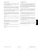


Table Of Contents
- Title Page
- Revision History
- Reader Comments
- Preface
- Table of Contents
- 1 - Safety
- 2 - Product Records and Maintenance
- 3 - Kubota Diesel Engine
- 4 - Hydraulic System
- Specifications
- General Information
- Hydraulic Schematic
- Hydraulic Flow Diagrams
- Special Tools
- Troubleshooting
- Testing
- Traction Circuit Relief Valve (R3) and (R4) Pressure Test
- Traction Circuit Charge Pressure Test
- Gear Pump (P3) Flow Test
- Front Wheel Motor Efficiency Test
- Piston (Traction) Pump Flow Test
- Relief Valve (PRV1) and (PRV2) Pressure Test
- Gear Pump (P1) and (P2) Flow Test
- Deck Motor Efficiency Test
- Lift Relief Valve (PRV) Pressure Test
- Gear Pump (P4) Flow Test
- Lift Cylinder Internal Leakage Test
- Steering Relief Valve (R10) Pressure Test
- Steering Cylinder Internal Leakage Test
- Service and Repairs
- General Precautions for Removing and Installing Hydraulic System Components
- Check Hydraulic Lines and Hoses
- Flush Hydraulic System
- Filtering Closed--Loop Traction Circuit
- Hydraulic System Start--up
- Hydraulic Reservoir
- Hydraulic Pump Drive Shaft
- Hydraulic Pump Assembly
- Piston (Traction) Pump Service
- Gear Pump Service
- Front Wheel Motors
- Rear Wheel Motors
- Wheel Motor Service
- CrossTrax AWD Manifold
- CrossTrax AWD Manifold Service
- Deck Control Manifold
- Deck Control Manifold Service
- Cutting Deck Motor
- Cutting Deck Motor Service
- Lift Control Manifold
- Lift Control Manifold Service
- Lift Cylinder
- Lift Cylinder Service
- Steering Control Valve
- Steering Control Valve Service
- Steering Cylinder
- Steering Cylinder Service
- Oil Cooler
- 5 - Electrical System
- General Information
- Special Tools
- Troubleshooting
- Electrical System Quick Checks
- Adjustments
- Component Testing
- Ignition Switch
- Indicator Lights
- Hour Meter
- Temperature Gauge
- PTO Switch
- Headlight Switch
- Seat Switch
- Joystick Raise and Lower Switches
- Traction Neutral Switch
- Parking Brake Switch
- Mow/Transport Switch
- Start Relay
- Main Power and Glow Relays
- Toro Electronic Controller (TEC)
- Fuses
- Diode Assembly
- Fusible Link Harness
- Hydraulic Solenoid Valve Coil
- Temperature Sender
- High Temperature Shutdown Switch
- Oil Pressure Switch
- Fuel Stop Solenoid
- Fuel Pump
- Service and Repairs
- 6 - Chassis
- 7 - Cutting Decks
- 8 - Foldout Drawings
- Hydraulic Schematic
- Electrical Schematic Sheet 1 of 2 (Serial numbers below 315000000)
- Electrical Schematic Sheet 2 of 2 (Serial numbers below 315000000)
- Eclectrical Schematic (Serial numbers 315000001 to 403430000)
- Eclectrical Schematic (Serial numbers above 403430001)
- Main Wire Harness Drawing (Serial numbers below 315000000)
- Main Wire Harness Diagram (Serial numbers below 315000000)
- Main Wiring Harness Drawing (Serial numbers 315000001 to 403430000)
- Main Wiring Harness Diagram (Serial numbers 315000001 to 403430000)
- Main Wiring Harness Drawing (Serial numbers 403430001 to 405699999)
- Main Wiring Harness Diagram (Serial numbers 403430001 to 405699999)
- Main Wiring Harness Drawing (Serial numbers above 405700000)
- Main Wiring Harness Diagram (Serial numbers above 405700000)
- Seat Wire Harness Drawing
- Seat Wire Harness Diagram
- Engine Wire Harness Drawing
- Engine Wire Harness Diagram

Groundsmaster 4300--DHydraulic System Page 4 -- 66
Hydraulic Pump Drive Shaft
1. Piston (traction) pump
2. Flange nut (2 used)
3. Flange head screw (2 used)
4. Guard hoop
5. Cap screw (2 used)
6. Engine flywheel
7. Cap screw (6 used)
8. Drive shaft assembly
9. Flange nut (4 used)
10. Flange head screw (2 used)
Figure 65
FRONT
RIGHT
34 to 42 ft--lb
(46to56N--m)
Antiseize
Lubricant
Permatex
Threadlocker
2
3
6
8
9
10
1
5
7
4
9