
Service Manual


Rev. D
Groundsmaster 4500--D/4700--D Cutting Units (Rev. B)Page 8 -- 21
Installation
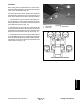
Each cutting deck is suspended from a carrier frame.
Decks should be attached to the carrier frame using the
lower hole in deck bracket (Fig. 20).
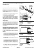
The cutting deck carrier frame is attached to the lift arm
and allows the cutting deck to pivot on the lift arm pivot
shaft. Carrier frames are secured to lift arms as follows:
1. Carrier frames for the front three cutting decks (#1,
#4, and #5) have a thrust washer between the carrier
frame and the lift arm. The frame is secured to the lift arm
pivot shaft with a lynch pin (Fig. 19).
2. Carrier frames for the center two cutting decks (#2
and #3) have a thrust washer between the carrier frame
and the lift arm. The frame is secured to the lift arm pivot
shaft with a rebound washer and cap screw (Fig. 19).
3. Carrier frames for the rear two cutting decks (#6 and
#7 on the GM4700--D) have a compression spring and
thrust washer between the carrier frame and the lift arm.
The frame is secured to the lift arm pivot shaft with a flat
washer and lock nut (Fig. 19).
1. Carrier frame
2. Lower hole
3. Deck bracket
Figure 20
2
1
3
Figure 21
#4 Deck #1 Deck #5 Deck
#7 Deck
(GM4700)
#6 Deck
(GM4700)
#3
Deck
#2
Deck
CUTTING DECK LOCATIONS
Cutting Units