
Operator's Manual

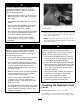


Figure19
1.Input5.Inseat
9.Output13.Start
2.Backlap
6.PTOswitch10.PTO
14.Power
3.Hightempshutdown
7.Parkbrakeoff11.Start
4.Hightempwarning(Not
used)
8.Neutral12.ETR
HerearethelogicaltroubleshootingstepsfortheSCM
device.
1.Determinetheoutputfaultyouaretryingtoresolve
(PTO,START,orETR).
2.Movekeyswitchto"ON"andensurethered
"power"LEDisilluminated.
3.MoveallinputswitchestoensureallLED’schange
state.
4.Positioninputdevicesatappropriatepositionto
achievetheappropriateoutput.Usethefollowing
logiccharttodeterminetheappropriateinput
condition.
5.IfspecicoutputLEDisilluminatedwithout
appropriateoutputfunction,checkoutputharness,
connections,andcomponent.Repairasrequired.
6.IfspecicoutputLEDisnotilluminated,check
bothfuses.
7.IfspecicoutputLEDisnotilluminatedandinputs
areinappropriatecondition,installnewSCMand
determineiffaultdisappears.
Eachrow(across)inthelogicchartbelowidenties
inputandoutputrequirementsforeachspecic
productfunction.Productfunctionsarelistedin
theleftcolumn.Symbolsidentifyspeciccircuit
conditionincluding:energizedtovoltage,closedto
ground,andopentoground.
Note:-Indicatesacircuitclosedtoground.-LEDON
OIndicatesacircuitopentogroundorde-energized-LEDOFF
+Indicatesanenergizedcircuit(clutchcoil,solenoid,orstartinput)LEDON.
""ABlankindicatesacircuitthatisnotinvolvedwiththelogic.
Totroubleshoot,turnonthekeywithoutstarting
theengine.Identifythespecicfunctionthatdoes
notworkandworkacrossthelogicchart.Inspect
theconditionofeachinputLED’stoensureit
matchesthelogicchart.
IftheinputLED’sarecorrect,checktheoutput
LED.IftheoutputLEDisilluminatedbutthe
27