
Service Manual


Groundsmaster 4300--D Hydraulic SystemPage 4 -- 81
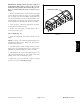
Removal (Fig. 75)
CAUTION
Before opening hydraulic system, operate all hy-
draulic controls to relieve system pressure and
avoid injury from pressurized hydraulic oil. See
Relieving Hydraulic System Pressure in the Gen-
eral Information section of this chapter.
1. Parkthe machine ona levelsurface, engage parking
brake, lower cutting decks and stop engine. Remove
key from the ignition switch.
2. Read the General Precautions for Removing and
Installing Hydraulic System Components at the begin-
ning of the Service and Repairs section of this chapter.
3. Chockfrontwheelsto prevent machine fromshifting.
4. Loosen, but do not remove, five (5) wheel lug nuts
and lock nut (item 14) that secures wheel hub to wheel
motor.
WARNING
Beforejackingupthe machine,review and follow
Jacking Instructions in Chapter 1 -- Safety.
5. Jack up machine enough to allow the removal of the
rear wheel. Support machine with jack stands.
6. Removerearwheelassemblyfromthemachine(see
RearWheelRemovalintheServiceandRepairssection
of Chapter 6 -- Chassis).
IMPORTANT: DO NOT hit wheel hub, wheel hub
puller or wheel motor with a hammer during wheel
motor removal or installation. Hammering may
cause damage to the wheel motor.
7. Make sure that lock nut (item 14) that secures wheel
hub to wheel motor is loosened at least two (2) turns.
Usehubpuller(seeSpecialToolsinthischapter)toloos-
en wheel hub from wheel motor.
8. Remove loosened lock nut and wheel hub from mo-
tor s haft. Discard lock nut. Locate and retrieve woodruff
key from wheel motor shaft.
9. Thoroughlycleanhydraulichoseendsandfittingson
rear wheel motor to prevent hydraulic system contami-
nation.
10.Label all hydraulic hoses for assembly purposes.
Remove hydraulic hoses from fittings on wheel motor.
Allow hoses to drain into a suitable container.
11.Putclean plugsin disconnectedhydraulic hosesand
fittings to prevent system contamination.
12.Supportthewheelmotortopreventitfromfallingdur-
ing removal.
13.Remove four (4) cap screws and lock washers that
secure wheel motor to the steering spindle.
14.Remove wheel motor from frame.
15.If necessary, remove hydraulic fittings from wheel
motor. Remove and discard O--rings from fittings.
Installation (Fig. 75)
IMPORTANT: Because of internal differences in
rear wheel motors, DO NOT interchange rear wheel
motors on machine (i.e. do not put right side motor
on left side of machine). The left side wheel motor
has a yellow identification mark on the motor hous-
ing. If necessary, use parts catalog and part number
on wheel motor to identify RH and LH motors.
1. If fittings were removed from wheel motor, lubricate
and install new O--rings to hydraulic fittings. Install fit-
tingsintowheelmotorports(seeHydraulic Fitting Instal-
lationin the GeneralInformation section ofthischapter).
2. Position rear wheel motor to steering spindle. Make
sure that ports in wheel motor are facing toward the rear
of the machine.
3. Secure wheel motor to spindle with four (4) cap
screws and lock washers.
4. Remove caps or plugs from disconnected hydraulic
hoses and wheel motor fittings that were placed during
wheel motor removal to prevent contamination.
5. Using labels placed during the removal process,
properly connecthydraulic hoses to wheel motor fittings
(see Hydraulic Hose and Tube Installationin the Gener-
al Information section of this chapter).
6. Make sure that tapers of wheel motor shaft and
wheel hub are thoroughly clean.
7. Positionwoodruffkeytokeyslotinwheelmotors haft.
IMPORTANT: Do not reuse lock nut that secures
wheelhub to wheelmotor after ithas been removed.
Hydraulic
System