
Service Manual


Groundsmaster 3500- D Hydraulic SystemPage 4 - 73
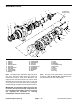
8. If hydraulic fittings are to be removed from wheel mo-
tor, mark fitting o rientation to allow correct assembly.
Installation (Fig. 75)
1. If hydraulic fittings were removed from wheel motor,
install f ittings to m otor using marks made during the r e-
moval process to properly orientate fittings.
2. Thoroughly clean wheel motor shaft and wheel hub
taper.
3. Lock wheel hub in a vise. Install woodruff key into the
wheel motor shaft. Slide motor shaft into hub and secure
with lock nut. Torque lock nut from 250 to 275 ft- lb (339
to 373 N- m). Remove wheel motor and h ub from vise.
4. Install wheel motor to the rear fork using Figure 75 as
guide.
5. Install tire and rim assembly to machine.
6. Lower the machine to the ground.
7. Torque rear wheel lug nuts from 45 to 65 ft- lb (61 to
88 N- m).
8. Make sure hydraulic tank is full. Add correct oil if nec-
essary (see Check Hydraulic System Fluid).
SafetyProduct Records
and Manuals
Kubota
Diesel Engine
Hydraulic
System
Electrical
System
Wheels, Brakes,
and Chassis