
Operator's Manual


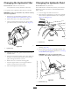


3.Removethelynchpinorretainingnutsecuringthe
deckcarrierframetothelift-arm-pivotpin(Figure64).
g031645
Figure64
1.Lynchpin
2.Lift-arm-pivotpin
4.Rollthecuttingdeckawayfromthetractionunit.
MountingtheMowerDecksto
theTractionUnit
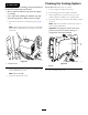
1.Performthepre-maintenanceprocedure;referto
PreparingtheMachineforMaintenance(page34).
2.Movethecuttingdeckintopositioninfrontofthe
tractionunit.
3.Slidethedeck-carrierframeontothelift-arm-pivot
pinandsecureitwiththelynchpinorretainingnut
(Figure64).
4.Usingthehydraulic-motor-mountingscrews,installthe
hydraulicmotortothedeck(Figure63).
Note:EnsurethattheO-ringisproperlypositioned
andnotdamaged.
5.Greasethespindle.
ServicingtheBladePlane
Therotarydeckcomesfromthefactorypresetat5cm(2
inches)height-of-cutandbladerakeof7.9mm(0.31inch).
Theleftandrightheightsofcutarealsopresettowithin±
0.7mm(0.03inch)oftheother.
Thecuttingdeckisdesignedtowithstandbladeimpacts
withoutdeformingthechamber.Ifthebladestrikesasolid
object,inspectthebladefordamageandthebladeplanefor
accuracy.
InspectingtheBladePlane
1.Removethehydraulicmotorfromthecuttingdeckand
removethecuttingdeckfromthetractor.
Note:Useahoist(oraminimumof2people)and
placethecuttingdeckonaattable.
2.Markanendofthebladewithapaintpenormarker.
Note:Usethisendofthebladetocheckallheights.
3.Positionthecuttingedgeofthemarkedendofthe
bladeatthe12o’clockposition(straightaheadinthe
directionofmowing)andmeasuretheheightfromthe
tabletothecuttingedgeoftheblade(Figure65).
G01 1353
6:00
12:00
9:00
3:00
g011353
Figure65
50