
Service Manual


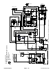


Table Of Contents
- Title Page
- Revision History
- Reader Comments
- Preface
- Table Of Contents
- 1 - Safety
- 2 - Product Records and Maintenance
- 3 - Kubota Diesel Engine (Model 30807)
- 4 - Kubota Gasoline Engine (Model 30809)
- 5 - Hydraulic System
- Specifications
- General Information
- Special Tools
- Hydraulic Schematics
- Hydraulic Flow Diagrams
- Troubleshooting
- Testing
- Traction Circuit Testing - Charge Pressure Test
- Traction Unit Testing - Wheel Motor Efficiency Tests
- Traction Circuit Testing - Piston Pump/Hydrostat (P3) Flow and Relief Pressure Test
- Cutting Deck Circuit Testing - Pressure Test
- Cutting Deck Circuit Testing - Deck Motor Efficiency/Case Drain Test
- Cutting Deck Circuit Testing - Manifold Relief Valve Pressure Test
- Cutting Deck Circuit Testing - Gear Pump (P1) Flow Test
- Steering/Lift/Sidewinder Circuit Testing - Gear Pump (P2) Flow Test
- Steering/Lift/Sidewinder Circuit Testing - Relief Valve Pressure Test
- Steering/Lift/Sidewinder Circuit Testing - Steering Control Valve and Steering Cylinder Test
- Adjustments
- Service and Repairs
- General Precautions for Removing and Installing Hydraulic System Components
- Check Hydraulic Lines and Hoses
- Priming Hydraulic Pumps
- Flush Hydraulic System
- Filtering Closed-Loop Traction Circuit
- Charge Hydraulic System
- Hydraulic Tank and Hydraulic Fluid Filter
- Hydraulic Fluid Cooler
- Piston Pump/Hydrostat Assembly
- Piston Pump/Hydrostat Service
- Gear Pump Service
- Front Wheel Motors
- Rear Wheel Motor
- Wheel Motor Service
- Hydraulic Manifold
- Hydraulic Manifold Service
- Cutting Deck Motor
- Cutting Deck Motor Service
- Steering Control Valve
- Steering Control Valve Service
- Steering Cylinder
- Steering Cylinder Service
- Lift/Sidewinder Control Valve
- Lift/Sidewinder Control Valve Service
- Front Lift Cylinder
- Rear Lift Cylinder
- Lift Cylinder Service
- Sidewinder
- 6 - Electrical System
- General Information
- Special Tools
- Troubleshooting
- Electrical System Quick Check
- Standard Control Module (SCM)
- Component Testing
- Ignition Switch
- Glow Controller (Diesel Engines Only)
- Glow Relay (Diesel Engine Only)
- Start/PWR/ETV Relays (Gasoline Engine Only)
- Hour Meter
- Diode Assemblies
- CAN-bus Termination Resistor (Gasoline Engines Only)
- Indicator Lights
- PTO Switch
- Neutral Switch
- Seat Switch
- Parking Brake and Transport/Mow Switches
- Fuses
- Fusible Links
- High Temperature Warning and Shutdown Switches (Diesel Engines Only)
- Oil Pressure Switch
- Fuel Pump (Diesel Engine Only)
- Fuel Pump (Gasoline Engine Only)
- Fuel Stop Solenoid (Diesel Engine Only)
- Electronic Throttle Control (Gasoline Engine Only)
- Hydraulic Cartridge Solenoid Valve Coils
- Service and Repairs
- 7 - Wheels, Brakes, and Chassis
- 8 - Cutting Decks
- 9 - Foldout Drawings
- Electrical Drawing Designations
- Groundsmaster 3500−D Hydraulic Schematic (Units Prior to Serial No. 314000001)
- Groundsmaster 3500−D Hydraulic Schematic (Unit Serial No. 314000001 & Up)
- Groundsmaster 3500−D Electrical Schematic (Serial Numbers Below 403440000)
- Groundsmaster 3500--DElectrical Schematic(Serial Numbers Above 403440001)
- Groundsmaster 3500−D Harness Diagram (Serial Numbers Below 403440000)
- Groundsmaster 3500−D Harness Drawing (Serial Numbers Below 403440000)
- Groundsmaster 3500--DHarness Diagram(Serial Numbers Above 403440001)
- Groundsmaster 3500--DWire Harness Diagram(Serial Numbers Above 403440001)
- Groundsmaster 3500−G Electrical Schematic (sheet 1 of 2)
- Groundsmaster 3500-G Electrical Schematic (sheet 2 of 2)
- Groundsmaster 3500−G Harness Diagram (Serial Numbers Below 402700000)
- Groundsmaster 3500−G Harness Drawing (Serial Numbers Below 402700000)
- Groundsmaster 3500--GHarness Drawing(Serial Numbers Above 402700001)
- Groundsmaster 3500--GWire Harness Drawing(Serial Numbers Above 402700001)

Groundsmaster 3500Hydraulic System Page 5 - 26
Sidewinder Circuit (Move Right - Extend)
High Pressure
Low Pressure (Charge)
Return or Suction
Flow
Groundmaster 3500
TRACTION WHEEL MOTORS
FORWARD
TOP PORT
INTERNAL CASE DRAIN
M6
M5
M4
MANIFOLD
BLOCK
OIL
COOLER
FILTER
OIL
T1
P1 CHG ST CR CF
PUMP
GEAR
P1
P2
STRAINER
LV
G2
OUT
IN
LV
LC1
T2
M2
S.W.
BULKHEAD
PLATE
D1 M1
AB C
M1
M2
M3
D
LIFT/S.W. VALVE
1000 psi
POWER STEERING VALVE
STEERING
SIDEWINDER
L
R
250 psi
V1
BACK
PRESSURE
LEFT
RIGHT
REAR
DECK
DECK
DECK
REAR FRONT
LIFT
S
3200
G1
RV
1500
LC2
psi
psi
P
T
E
200- 300 psi
3500 psi
100- 150 psi
UPPER
PORT
LOWER
PORT
HYDROSTAT
BY- PASS
VALVE
P3
G2 G1
NOTE: Hydraulic Schematic for Unit Serial No. 314000001 & Up Shown