
Service Manual


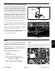
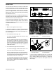


Table Of Contents
- Title Page
- Revision History
- Reader Comments
- Preface
- Table Of Contents
- 1 - Safety
- 2 - Product Records and Maintenance
- 3 - Kubota Diesel Engine (Model 30807)
- 4 - Kubota Gasoline Engine (Model 30809)
- 5 - Hydraulic System
- Specifications
- General Information
- Special Tools
- Hydraulic Schematics
- Hydraulic Flow Diagrams
- Troubleshooting
- Testing
- Traction Circuit Testing - Charge Pressure Test
- Traction Unit Testing - Wheel Motor Efficiency Tests
- Traction Circuit Testing - Piston Pump/Hydrostat (P3) Flow and Relief Pressure Test
- Cutting Deck Circuit Testing - Pressure Test
- Cutting Deck Circuit Testing - Deck Motor Efficiency/Case Drain Test
- Cutting Deck Circuit Testing - Manifold Relief Valve Pressure Test
- Cutting Deck Circuit Testing - Gear Pump (P1) Flow Test
- Steering/Lift/Sidewinder Circuit Testing - Gear Pump (P2) Flow Test
- Steering/Lift/Sidewinder Circuit Testing - Relief Valve Pressure Test
- Steering/Lift/Sidewinder Circuit Testing - Steering Control Valve and Steering Cylinder Test
- Adjustments
- Service and Repairs
- General Precautions for Removing and Installing Hydraulic System Components
- Check Hydraulic Lines and Hoses
- Priming Hydraulic Pumps
- Flush Hydraulic System
- Filtering Closed-Loop Traction Circuit
- Charge Hydraulic System
- Hydraulic Tank and Hydraulic Fluid Filter
- Hydraulic Fluid Cooler
- Piston Pump/Hydrostat Assembly
- Piston Pump/Hydrostat Service
- Gear Pump Service
- Front Wheel Motors
- Rear Wheel Motor
- Wheel Motor Service
- Hydraulic Manifold
- Hydraulic Manifold Service
- Cutting Deck Motor
- Cutting Deck Motor Service
- Steering Control Valve
- Steering Control Valve Service
- Steering Cylinder
- Steering Cylinder Service
- Lift/Sidewinder Control Valve
- Lift/Sidewinder Control Valve Service
- Front Lift Cylinder
- Rear Lift Cylinder
- Lift Cylinder Service
- Sidewinder
- 6 - Electrical System
- General Information
- Special Tools
- Troubleshooting
- Electrical System Quick Check
- Standard Control Module (SCM)
- Component Testing
- Ignition Switch
- Glow Controller (Diesel Engines Only)
- Glow Relay (Diesel Engine Only)
- Start/PWR/ETV Relays (Gasoline Engine Only)
- Hour Meter
- Diode Assemblies
- CAN-bus Termination Resistor (Gasoline Engines Only)
- Indicator Lights
- PTO Switch
- Neutral Switch
- Seat Switch
- Parking Brake and Transport/Mow Switches
- Fuses
- Fusible Links
- High Temperature Warning and Shutdown Switches (Diesel Engines Only)
- Oil Pressure Switch
- Fuel Pump (Diesel Engine Only)
- Fuel Pump (Gasoline Engine Only)
- Fuel Stop Solenoid (Diesel Engine Only)
- Electronic Throttle Control (Gasoline Engine Only)
- Hydraulic Cartridge Solenoid Valve Coils
- Service and Repairs
- 7 - Wheels, Brakes, and Chassis
- 8 - Cutting Decks
- 9 - Foldout Drawings
- Electrical Drawing Designations
- Groundsmaster 3500−D Hydraulic Schematic (Units Prior to Serial No. 314000001)
- Groundsmaster 3500−D Hydraulic Schematic (Unit Serial No. 314000001 & Up)
- Groundsmaster 3500−D Electrical Schematic (Serial Numbers Below 403440000)
- Groundsmaster 3500--DElectrical Schematic(Serial Numbers Above 403440001)
- Groundsmaster 3500−D Harness Diagram (Serial Numbers Below 403440000)
- Groundsmaster 3500−D Harness Drawing (Serial Numbers Below 403440000)
- Groundsmaster 3500--DHarness Diagram(Serial Numbers Above 403440001)
- Groundsmaster 3500--DWire Harness Diagram(Serial Numbers Above 403440001)
- Groundsmaster 3500−G Electrical Schematic (sheet 1 of 2)
- Groundsmaster 3500-G Electrical Schematic (sheet 2 of 2)
- Groundsmaster 3500−G Harness Diagram (Serial Numbers Below 402700000)
- Groundsmaster 3500−G Harness Drawing (Serial Numbers Below 402700000)
- Groundsmaster 3500--GHarness Drawing(Serial Numbers Above 402700001)
- Groundsmaster 3500--GWire Harness Drawing(Serial Numbers Above 402700001)

Groundsmaster 3500Page 6 − 24Electrical System
High Temperature Warning and Shutdown Switches (Diesel Engines Only)
The high temperature warning and shutdown switches
are located on the water pump housing, which is located
on the rear end of the engine block (alternator end) (Fig.
31).
CAUTION
Make sure engine is cool before removing the
temperature switch.
1. Lower coolant level in the engine and remove the
temperature switch.
2. Put switch in a container of oil with a thermometer
and slowly heat the oil (Fig. 32).
CAUTION
Handle the hot oil with extreme care to prevent
personal injury or fire.
3. Check continuity of the switch with a multimeter
(ohms setting).
A. The high temperature warning switch is normally
open and should close between 216 to 226F (102 to
108C).
B. The high temperature shutdown switch is normal-
ly open and should close between 225 to 235F (107
to 113C).
4. Allow oil to cool while observing temperature.
A. The high temperature warning switch should
open at about 208F (98C).
B. The high temperature shutdown switch should
open at about 219F (104C).
5. Replace switch if necessary.
1. Temp. warning switch
2. Temp. shutdown switch
3. Water pump housing
Figure 31
2
1
3
Figure 32
VOA