
Operator's Manual


g006926
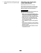
Figure73
1.Sharpenatthisangleonly
4.Tocheckthebladeforbeingstraightandparallel,
laythebladeonalevelsurfaceandcheckits
ends.Theendsoftheblademustbeslightly
lowerthanthecenter,andthecuttingedgemust
belowerthantheheeloftheblade.Thisblade
willproducegoodqualityofcutandrequire
minimalpowerfromtheengine.Bycontrasta
bladethatishigherattheendsthanthecenter,
orifcuttingedgeishigherthantheheel,the
bladeisbentorwarpedandmustbereplaced.
5.Installtheblade,sailfacingtowardcuttingdeck,
withtheanti-scalpcupandbladebolt.Tighten
thebladeboltto115–149N-m(85–110ft-lb).
CheckingtheBladeStoppingTime
ServiceInterval:Beforeeachuseordaily
Thebladesofthecuttingdeckshouldcometoa
completestopinapproximately5secondsafteryou
shutdownthecuttingdeckengagementswitch.
Note:Makesurethedecksareloweredontoaclean
sectionofturforhardsurfacetoavoidthrowndust
anddebris.
Toverifythisstoppingtime,haveasecondperson
standbackfromthedeckatleast6m(20feet)and
watchthebladesononeofthecuttingdecks.Have
theoperatorshutthecuttingdecksdownandrecord
thetimeittakesforthebladestocometoacomplete
stop.Ifthistimeisgreaterthan7seconds,thebraking
valveneedsadjustment.CallyourT oroDistributorfor
assistanceinmakingthisadjustment.
ServicingtheFrontRoller
Inspectthefrontrollerforwear,excesswobble,or
binding.Serviceorreplacetherollerorcomponentsif
anyoftheseconditionsexist.
DisassemblingtheFrontRoller
1.Removetherollermountingbolt(Figure74).
2.Insertapunchthroughtheendoftheroller
housinganddrivetheoppositebearingoutby
alternatingtapstotheoppositesideofinner
bearingrace.Thereshouldbea1.5mm(0.060
inch)lipofinnerraceexposed.
g011356
Figure74
1.Frontroller3.Bearing
2.Mountingbolt4.Bearingspacer
3.Pushthesecondbearingoutinpress.
4.Inspecttherollerhousing,bearings,andbearing
spacerfordamage(Figure74).Replace
damagedcomponentsandassemble.
AssemblingtheFrontRoller
1.Presstherstbearingintotherollerhousing
(Figure74).Pressontheouterraceonlyor
equallyontheinnerandouterrace.
2.Insertthespacer(Figure74).
3.Pressthesecondbearingintotherollerhousing
(Figure74)pressingequallyontheinnerand
outerraceuntiltheinnerracecomesincontact
withthespacer.
4.Installtherollerassemblyintothedeckframe.
Important:Securingtherollerassembly
withagaplargerthan1.5mm(0.060inch)
createsasideloadonthebearingandcan
leadtoprematurebearingfailure
5.Verifythatthereisnomorethana1.5mm(0.060
inch)gapbetweenrollerassemblyandtheroller
mountbracketsofthedeckframe.Ifthereisa
gapover1.5mm(0.060inch),installenough5/8
inchdiameterwasherstotakeuptheslop.
6.Securethemountingboltto108N-m(80ft-lb).
60