
Operator's Manual


CuttingDeck
Maintenance
SeparatingtheCutting
DecksfromtheTraction
Unit
1.Positionthemachineonalevelsurface,lower
thecuttingdeckstotheoor,shuttheengineoff,
andengagetheparkingbrake.
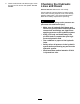
2.Disconnectandremovethehydraulicmotor
fromthedeck(Figure67).Coverthetopofthe
spindletopreventcontamination.
g011351
Figure67
1.Motormountingscrews
3.Removethelynchpinorretainingnutsecuring
thedeckcarrierframetotheliftarmpivotpin
(Figure68).
g011352
Figure68
1.Lynchpin
2.Liftarmpivotpin
4.Rollthecuttingdeckawayfromthetractionunit.
MountingtheCuttingDecks
totheTractionUnit
1.Positionmachineonalevelsurfaceandshut
engineoff.
2.Movecuttingdeckintopositioninfrontoftraction
unit.
3.Slidedeckcarrierframeontoliftarmpivotpin.
Securewithlynchpinorretainingnut(Figure
68).
4.Installthehydraulicmotortothedeck(Figure
67).MakesurethattheO-ringisinpositionand
notdamaged.
5.Greasethespindle.
ServicingtheBladePlane
Therotarydeckcomesfromthefactorypresetat5cm
(2.00inch)height-of-cutandbladerakeof7.9mm
(0.310inch).Theleft-handandright-handheights
arealsopresettowithin±0.7mm(0.030inch)ofthe
other.
Thecuttingdeckisdesignedtowithstandblade
impactswithoutdeformationofthechamber.Ifasolid
objectisstruck,inspectthebladefordamageandthe
bladeplaneforaccuracy.
InspectingtheBladePlane
1.Removethehydraulicmotorfromthecutting
deckandremovethecuttingdeckfromthe
tractor.
2.Useahoist(orminimumoftwopeople)and
placethecuttingdeckonaattable
3.Markoneendofthebladewithapaintpenor
marker.Usethisendofthebladetocheckall
heights.
4.Positionthecuttingedgeofthemarkedendof
thebladeat12o’clock(straightaheadinthe
directionofmowing)(Figure69)andmeasure
heightfromtabletocuttingedgeofblade.
57