
Service Manual


B
B
A
23
32
30
29
3426
25
27
24
24
28
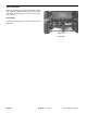
0.34 ± ″
″
25
l
Apply
Never-seeze
Detail A Detail B
0.03
0.040 MAX
Arrow end of roller
clutches must face
6-bolt f ange end of
clutch housing
toward rear axle)
Figure 9
6. Install clutch assembly onto yoke shaft, then install
ot
her thrust washer. Install retaining ring (Item 23) to
secure clutch assembly to shaft. Install axle coupling
(Item 32) to clutch housing with six (6) capscrews and
lockwashers, then tighten capscrews evenly.
7. Lubricate clutch through grease fitting with No. 2
Ge
neral Purpose Lithium Grease.
Installing Drive Shaft.
1. Apply never-seize to splines of traction shaft and axle
in
put shaft.
2. Slide clutch end of drive shaft onto rear axle shaft
splin
e, aligning roll pin hole in shaft with hole in axle
coupling. Install roll pin (Item 29) through coupling and
shaft.
3. Tighten two (2) capscrews (Item 35) and locknuts
(I
tem 31) to secure coupling to shaft.
4. Secure drive shaft yoke flange to flange on front axle
differential with six (6) socekt head capscrews and
lockwashers (not shown).
Repairs Pa
ge 14 - 6
Rev. B
Groundsmaster
®
223-D